
En esta sección se describen los ejes de los sensores, los sensores básicos y los sensores compuestos (actividad, actitud, sin calibrar e interacción).
Ejes sensores
Los valores de eventos de sensor de muchos sensores se expresan en un marco específico que es estático en relación con el dispositivo.
Ejes de dispositivos móviles
La API del sensor es relativa solo a la orientación natural de la pantalla (los ejes no se intercambian cuando cambia la orientación de la pantalla del dispositivo).

Figura 1. Sistema de coordenadas (relativo a un dispositivo móvil) utilizado por Sensor API
Hachas automotrices
En las implementaciones de Android Automotive, los ejes se definen con respecto al marco de la carrocería del vehículo. El origen del marco de referencia del vehículo es el centro del eje trasero. El marco de referencia del vehículo está orientado de modo que:
- El eje X apunta a la derecha y está en un plano horizontal, perpendicular al plano de simetría del vehículo.
- El eje Y apunta hacia adelante y está en un plano horizontal.
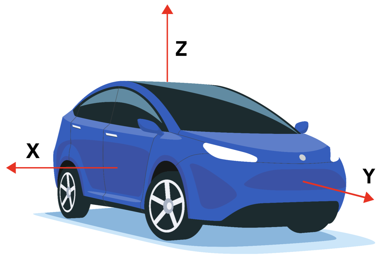
Figura 2. Sistema de coordenadas (relativo a un dispositivo automotriz) utilizado por Sensor API
El marco de referencia del vehículo es un sistema de coordenadas diestro. Por lo tanto, el eje Z apunta hacia arriba.
El eje Z del marco de referencia está alineado con la gravedad, lo que significa que tanto el eje X como el eje Y son horizontales. Como resultado, es posible que el eje Y no siempre pase por el eje delantero.
Sensores básicos
Los tipos de sensores base reciben el nombre de los sensores físicos que representan. Estos sensores transmiten datos de un solo sensor físico (a diferencia de los sensores compuestos que generan datos a partir de otros sensores). Los ejemplos de tipos de sensores básicos incluyen:
-
SENSOR_TYPE_ACCELEROMETER -
SENSOR_TYPE_GYROSCOPE -
SENSOR_TYPE_MAGNETOMETER
Sin embargo, los sensores base no son iguales y no deben confundirse con su sensor físico subyacente. Los datos de un sensor base no son la salida sin procesar del sensor físico porque se aplican correcciones (como compensación de polarización y compensación de temperatura).
Por ejemplo, las características de un sensor base pueden ser diferentes de las características de su sensor físico subyacente en los siguientes casos de uso:
- Un chip de giroscopio calificado para tener un rango de polarización de 1 grado/seg.
- Después de aplicar la calibración de fábrica, la compensación de temperatura y la compensación de sesgo, el sesgo real del sensor de Android se reducirá, puede llegar a un punto en el que se garantice que el sesgo será inferior a 0,01 grados/seg.
- En esta situación, decimos que el sensor de Android tiene un sesgo por debajo de 0,01 grados por segundo, aunque la hoja de datos del sensor subyacente indica 1 grado por segundo.
- Un barómetro con un consumo de energía de 100 uW.
- Debido a que los datos generados deben transportarse desde el chip al SoC, el costo de energía real para recopilar datos del sensor del barómetro de Android podría ser mucho mayor, por ejemplo, 1000 uW.
- En esta situación, decimos que el sensor de Android tiene un consumo de energía de 1000 uW, aunque el consumo de energía medido en los cables del chip barómetro es de 100 uW.
- Un magnetómetro que consume 100uW al calibrar, pero consume más al calibrar.
- Su rutina de calibración puede requerir activar el giroscopio, consumiendo 5000 uW, y ejecutando algún algoritmo, costando otros 900 uW.
- En esta situación, decimos que el consumo máximo de energía del sensor Android (magnetómetro) es de 6000 uW.
- En este caso, el consumo de energía promedio es la medida más útil y es lo que se informa en las características estáticas del sensor a través del HAL.
Acelerómetro
Modo de informe: continuo
getDefaultSensor(SENSOR_TYPE_ACCELEROMETER) devuelve un sensor que no es de activación
Un sensor acelerómetro informa la aceleración del dispositivo a lo largo de los tres ejes del sensor. La aceleración medida incluye tanto la aceleración física (cambio de velocidad) como la gravedad. La medición se informa en los campos x, y y z de sensores_event_t.acceleration.
Todos los valores están en unidades SI (m/s^2) y miden la aceleración del dispositivo menos la fuerza de la gravedad a lo largo de los tres ejes del sensor.
Aquí hay ejemplos:
- La norma de (x, y, z) debe estar cerca de 0 cuando está en caída libre.
- Cuando el dispositivo se encuentra plano sobre una mesa y se empuja sobre su lado izquierdo hacia la derecha, el valor de la aceleración x es positivo.
- Cuando el dispositivo se encuentra plano sobre una mesa, el valor de aceleración a lo largo de z es +9,81 alo, que corresponde a la aceleración del dispositivo (0 m/s^2) menos la fuerza de la gravedad (-9,81 m/s^2).
- Cuando el dispositivo se encuentra plano sobre una mesa y se empuja hacia el cielo, el valor de la aceleración es superior a +9,81, que corresponde a la aceleración del dispositivo (+A m/s^2) menos la fuerza de la gravedad (-9,81 m /s^2).
Las lecturas se calibran usando:
- Compensación de temperatura
- Calibración de polarización en línea
- Calibración de báscula en línea
La calibración de sesgo y escala solo debe actualizarse mientras el sensor está desactivado, para evitar que se produzcan saltos en los valores durante la transmisión.
El acelerómetro también informa qué tan precisa espera que sean sus lecturas a través de sensors_event_t.acceleration.status . Consulte las SensorManager SENSOR_STATUS_* de SensorManager para obtener más información sobre los valores posibles para este campo.
Temperatura ambiente
Modo de informe: Al cambiar
getDefaultSensor(SENSOR_TYPE_AMBIENT_TEMPERATURE) devuelve un sensor que no es de activación
Este sensor proporciona la temperatura ambiente (habitación) en grados Celsius.
Sensor de campo magnético
Modo de informe: continuo
getDefaultSensor(SENSOR_TYPE_MAGNETIC_FIELD) devuelve un sensor que no es de activación
SENSOR_TYPE_GEOMAGNETIC_FIELD == SENSOR_TYPE_MAGNETIC_FIELD
Un sensor de campo magnético (también conocido como magnetómetro) informa el campo magnético ambiental, medido a lo largo de los tres ejes del sensor.
La medición se informa en los campos x, y y z de sensors_event_t.magnetic y todos los valores están en micro-Tesla (uT).
El magnetómetro también informa qué tan precisa espera que sean sus lecturas a través de sensors_event_t.magnetic.status . Consulte las SensorManager SENSOR_STATUS_* de SensorManager para obtener más información sobre los valores posibles para este campo.
Las lecturas se calibran usando:
- Compensación de temperatura
- Calibración de hierro dulce de fábrica (o en línea)
- Calibración en línea de hierro duro
Giroscopio
Modo de informe: continuo
getDefaultSensor(SENSOR_TYPE_GYROSCOPE) devuelve un sensor que no es de activación
Un sensor de giroscopio informa la velocidad de rotación del dispositivo alrededor de los tres ejes del sensor.
La rotación es positiva en sentido antihorario (regla de la mano derecha). Es decir, un observador que mira desde alguna ubicación positiva en el eje x, y o z a un dispositivo colocado en el origen informaría una rotación positiva si el dispositivo parece estar girando en sentido contrario a las agujas del reloj. Tenga en cuenta que esta es la definición matemática estándar de rotación positiva y no concuerda con la definición aeroespacial de balanceo.
La medición se informa en los campos x, y y z de sensors_event_t.gyro y todos los valores están en radianes por segundo (rad/s).
Las lecturas se calibran usando:
- Compensación de temperatura
- Compensación de escala de fábrica (o en línea)
- Calibración de sesgo en línea (para eliminar la deriva)
El giroscopio también informa qué tan precisa espera que sean sus lecturas a través de sensors_event_t.gyro.status . Consulte las SensorManager SENSOR_STATUS_* de SensorManager para obtener más información sobre los valores posibles para este campo.
El giroscopio no se puede emular en función de magnetómetros y acelerómetros, ya que esto provocaría una consistencia y capacidad de respuesta locales reducidas. Debe basarse en un chip de giroscopio habitual.
Ritmo cardiaco
Modo de informe: Al cambiar
getDefaultSensor(SENSOR_TYPE_HEART_RATE) devuelve un sensor que no es de activación
Un sensor de frecuencia cardíaca informa la frecuencia cardíaca actual de la persona que toca el dispositivo.
La frecuencia cardíaca actual en latidos por minuto (BPM) se informa en sensors_event_t.heart_rate.bpm y el estado del sensor se informa en sensors_event_t.heart_rate.status . Consulte las SensorManager SENSOR_STATUS_* de SensorManager para obtener más información sobre los valores posibles para este campo. En particular, en la primera activación, a menos que se sepa que el dispositivo no está en el cuerpo, el campo de estado del primer evento debe establecerse en SENSOR_STATUS_UNRELIABLE . Debido a que este sensor cambia, los eventos se generan cuando y solo cuando heart_rate.bpm o heart_rate.status han cambiado desde el último evento. Los eventos no se generan más rápido que cada período de sampling_period .
sensor_t.requiredPermission siempre es SENSOR_PERMISSION_BODY_SENSORS .
Luz
Modo de informe: Al cambiar
getDefaultSensor(SENSOR_TYPE_LIGHT) devuelve un sensor que no es de activación
Un sensor de luz informa la iluminación actual en unidades SI lux.
La medición se informa en sensors_event_t.light .
Proximidad
Modo de informe: Al cambiar
Por lo general, se define como un sensor de activación
getDefaultSensor(SENSOR_TYPE_PROXIMITY) devuelve un sensor de activación
Un sensor de proximidad informa la distancia desde el sensor hasta la superficie visible más cercana.
Hasta Android 4.4, los sensores de proximidad siempre eran sensores de activación, activando el SoC al detectar un cambio en la proximidad. Después de Android 4.4, recomendamos implementar primero la versión de activación de este sensor, ya que es el que se usa para encender y apagar la pantalla mientras se realizan llamadas telefónicas.
La medida se informa en centímetros en sensors_event_t.distance . Tenga en cuenta que algunos sensores de proximidad solo admiten una medición binaria "cercana" o "lejana". En este caso, el sensor informa su valor sensor_t.maxRange en el estado "lejos" y un valor menor que sensor_t.maxRange en el estado "cerca".
Presión
Modo de informe: continuo
getDefaultSensor(SENSOR_TYPE_PRESSURE) devuelve un sensor que no es de activación
Un sensor de presión (también conocido como barómetro) informa la presión atmosférica en hectopascales (hPa).
Las lecturas se calibran usando
- Compensación de temperatura
- Calibración de polarización de fábrica
- Calibración de báscula de fábrica
El barómetro se usa a menudo para estimar los cambios de elevación. Para estimar la elevación absoluta, se debe usar como referencia la presión a nivel del mar (que cambia según el clima).
Humedad relativa
Modo de informe: Al cambiar
getDefaultSensor(SENSOR_TYPE_RELATIVE_HUMIDITY) devuelve un sensor que no es de activación
Un sensor de humedad relativa mide la humedad relativa del aire ambiental y devuelve un valor en porcentaje.
Tipos de sensores compuestos
Un sensor compuesto genera datos procesando y/o fusionando datos de uno o varios sensores físicos. (Cualquier sensor que no sea un sensor base se denomina sensor compuesto). Los ejemplos de sensores compuestos incluyen:
- Detector de pasos y movimiento significativo , que generalmente se basan en un acelerómetro, pero también podrían basarse en otros sensores, si el consumo de energía y la precisión fueran aceptables.
- Vector de rotación del juego , basado en un acelerómetro y un giroscopio.
- Giroscopio no calibrado , que es similar al sensor base del giroscopio, pero la calibración de sesgo se informa por separado en lugar de corregirse en la medición.
Al igual que con los sensores base, las características de los sensores compuestos provienen de las características de sus datos finales. Por ejemplo, el consumo de energía de un vector de rotación del juego es probablemente igual a la suma de los consumos de energía del chip del acelerómetro, el chip del giroscopio, el chip que procesa los datos y los buses que transportan los datos. Como otro ejemplo, la deriva de un vector de rotación del juego depende tanto de la calidad del algoritmo de calibración como de las características físicas del sensor.
La siguiente tabla enumera los tipos de sensores compuestos disponibles. Cada sensor compuesto se basa en datos de uno o varios sensores físicos. Evite elegir otros sensores físicos subyacentes para aproximar los resultados, ya que brindan una experiencia de usuario deficiente.
| Tipo de sensor | Categoría | Sensores físicos subyacentes | Modo de informe |
|---|---|---|---|
Actitud | Acelerómetro, giroscopio, NO DEBE UTILIZAR magnetómetro | Continuo | |
Actitud | Acelerómetro, magnetómetro, NO DEBE UTILIZAR giroscopio | Continuo | |
| gesto de mirada | Interacción | Indefinido | Un trago |
Actitud | Acelerómetro, giroscopio | Continuo | |
sin calibrar | Giroscopio | Continuo | |
Actividad | Acelerómetro, giroscopio (si está presente) o magnetómetro (si no hay giroscopio) | Continuo | |
sin calibrar | Magnetómetro | Continuo | |
Orientación (en desuso) | Actitud | Acelerómetro, magnetómetro, giroscopio (si está presente) | Continuo |
Interacción | Indefinido | Un trago | |
Actitud | Acelerómetro, magnetómetro, giroscopio | Continuo | |
Actividad | Acelerómetro (u otro siempre que sea de muy baja potencia) | Un trago | |
Actividad | Acelerómetro | en el cambio | |
Actividad | Acelerómetro | Especial | |
Actividad | Acelerómetro | Especial | |
Interacción | Indefinido | Un trago |
![]() = Sensor de baja potencia
= Sensor de baja potencia
Sensores compuestos de actividad
Aceleración lineal
Sensores físicos subyacentes: acelerómetro y (si está presente) giroscopio (o magnetómetro si no hay giroscopio)
Modo de informe: continuo
getDefaultSensor(SENSOR_TYPE_LINEAR_ACCELERATION) devuelve un sensor que no es de activación
Un sensor de aceleración lineal informa la aceleración lineal del dispositivo en el marco del sensor, sin incluir la gravedad.
La salida es conceptualmente: salida del acelerómetro menos la salida del sensor de gravedad . Se informa en m/s^2 en los campos x, y y z de sensors_event_t.acceleration .
Las lecturas en todos los ejes deben estar cerca de 0 cuando el dispositivo está inmóvil.
Si el dispositivo posee un giroscopio, el sensor de aceleración lineal debe usar el giroscopio y el acelerómetro como entrada.
Si el dispositivo no posee un giroscopio, el sensor de aceleración lineal debe usar el acelerómetro y el magnetómetro como entrada.
Movimiento significativo
Sensor físico subyacente: Acelerómetro (u otro siempre que sea de baja potencia)
Modo de informe: One-shot
Baja potencia
Implemente solo la versión de activación de este sensor.
getDefaultSensor(SENSOR_TYPE_SIGNIFICANT_MOTION) devuelve un sensor de activación
Un detector de movimiento significativo se activa cuando detecta un movimiento significativo : un movimiento que podría provocar un cambio en la ubicación del usuario.
Ejemplos de tales movimientos significativos son:
- Caminar o andar en bicicleta
- Sentado en un automóvil, autobús o tren en movimiento
Ejemplos de situaciones que no desencadenan un movimiento significativo:
- Teléfono en el bolsillo y la persona no se mueve
- El teléfono está sobre una mesa y la mesa tiembla un poco debido al tráfico cercano o a la lavadora
En el nivel alto, el detector de movimiento significativo se usa para reducir el consumo de energía de la determinación de la ubicación. Cuando los algoritmos de localización detectan que el dispositivo está estático, pueden cambiar a un modo de bajo consumo, donde dependen de un movimiento significativo para activar el dispositivo cuando el usuario cambia de ubicación.
Este sensor debe ser de baja potencia. Hace una compensación por el consumo de energía que puede resultar en una pequeña cantidad de falsos negativos. Esto se hace por algunas razones:
- El objetivo de este sensor es ahorrar energía.
- Activar un evento cuando el usuario no se está moviendo (falso positivo) es costoso en términos de energía, por lo que debe evitarse.
- No activar un evento cuando el usuario se está moviendo (falso negativo) es aceptable siempre que no se haga repetidamente. Si el usuario ha estado caminando durante 10 segundos, no es aceptable no activar un evento dentro de esos 10 segundos.
Cada evento de sensor informa 1 en sensors_event_t.data[0] .
detector de paso
Sensor físico subyacente: Acelerómetro (+ posiblemente otros, siempre que sea de baja potencia)
Modo de informe: especial (un evento por paso dado)
Baja potencia
getDefaultSensor(SENSOR_TYPE_STEP_DETECTOR) devuelve un sensor que no es de activación
Un detector de pasos genera un evento cada vez que el usuario da un paso.
La marca de tiempo del evento sensors_event_t.timestamp corresponde al momento en que el pie toca el suelo, generando una gran variación en la aceleración.
En comparación con el contador de pasos, el detector de pasos debe tener una latencia más baja (menos de dos segundos). Tanto el detector de pasos como el contador de pasos detectan cuando el usuario camina, corre y sube las escaleras. No deberían activarse cuando el usuario está andando en bicicleta, conduciendo o en otros vehículos.
Este sensor debe ser de baja potencia. Es decir, si la detección de pasos no se puede hacer en hardware, no se debe definir este sensor. En particular, cuando el detector de pasos está activado y el acelerómetro no, solo los pasos deben activar interrupciones (no todas las lecturas del acelerómetro).
sampling_period_ns no tiene impacto en los detectores de pasos.
Cada evento de sensor informa 1 en sensors_event_t.data[0] .
Contador de pasos
Sensor físico subyacente: Acelerómetro (+ posiblemente otros, siempre que sea de baja potencia)
Modo de informe: Al cambiar
bajo consumo
getDefaultSensor(SENSOR_TYPE_STEP_COUNTER) devuelve un sensor que no es de activación
Un contador de pasos informa el número de pasos dados por el usuario desde el último reinicio mientras estaba activado.
La medición se informa como uint64_t en sensors_event_t.step_counter y se restablece a cero solo en un reinicio del sistema.
La marca de tiempo del evento se establece en el momento en que se realizó el último paso para ese evento.
Consulte el tipo de sensor Detector de pasos para conocer el significado del tiempo de un paso.
En comparación con el detector de pasos, el contador de pasos puede tener una latencia más alta (hasta 10 segundos). Gracias a esta latencia, este sensor tiene una alta precisión; el conteo de pasos después de un día completo de medidas debe estar dentro del 10% del conteo de pasos real. Tanto el detector de pasos como el contador de pasos detectan cuando el usuario camina, corre y sube las escaleras. No deberían activarse cuando el usuario está andando en bicicleta, conduciendo o en otros vehículos.
El hardware debe garantizar que el conteo interno de pasos nunca se desborde. El tamaño mínimo del contador interno del hardware será de 16 bits. En caso de desbordamiento inminente (como máximo cada ~2^16 pasos), el SoC se puede activar para que el controlador pueda realizar el mantenimiento del contador.
Como se indica en Interacción , mientras este sensor funcione, no interrumpirá a ningún otro sensor, en particular, el acelerómetro, que muy bien podría estar en uso.
Si un dispositivo en particular no es compatible con estos modos de operación, HAL no debe informar sobre este tipo de sensor. Es decir, no es aceptable "emular" este sensor en el HAL.
Este sensor debe ser de baja potencia. Es decir, si la detección de pasos no se puede realizar en hardware, este sensor no debe definirse. En particular, cuando el contador de pasos está activado y el acelerómetro no, solo los pasos deben activar las interrupciones (no los datos del acelerómetro).
Detector de inclinación
Sensor físico subyacente: Acelerómetro (+ posiblemente otros, siempre que sea de baja potencia)
Modo de informe: Especial
bajo consumo
Implemente solo la versión de activación de este sensor.
getDefaultSensor(SENSOR_TYPE_TILT_DETECTOR) devuelve un sensor de activación
Un detector de inclinación genera un evento cada vez que se detecta un evento de inclinación.
Un evento de inclinación se define por la dirección de la gravedad promedio de la ventana de 2 segundos que cambia al menos 35 grados desde la activación o el último evento generado por el sensor. Aquí está el algoritmo:
-
reference_estimated_gravity= promedio de las mediciones del acelerómetro durante el primer segundo después de la activación o la gravedad estimada cuando se generó el último evento de inclinación. -
current_estimated_gravity= promedio de las mediciones del acelerómetro en los últimos 2 segundos. - Activar cuando el
angle(reference_estimated_gravity, current_estimated_gravity) > 35 degrees
Las grandes aceleraciones sin un cambio en la orientación del teléfono no deberían desencadenar un evento de inclinación. Por ejemplo, un giro brusco o una fuerte aceleración mientras conduce un automóvil no debería desencadenar un evento de inclinación, aunque el ángulo de la aceleración promedio puede variar en más de 35 grados. Por lo general, este sensor se implementa con la ayuda de solo un acelerómetro. También se pueden usar otros sensores si no aumentan significativamente el consumo de energía. Este es un sensor de baja potencia que debería permitir que el SoC entre en modo de suspensión. No emule este sensor en el HAL. Cada evento de sensor informa 1 en sensors_event_t.data[0] .
Sensores compuestos de actitud
vector de rotación
Sensores físicos subyacentes: acelerómetro, magnetómetro y giroscopio
Modo de informe: continuo
getDefaultSensor(SENSOR_TYPE_ROTATION_VECTOR) devuelve un sensor que no es de activación
Un sensor de vector de rotación informa la orientación del dispositivo en relación con el marco de coordenadas Este-Norte-Arriba. Por lo general, se obtiene mediante la integración de lecturas de acelerómetro, giroscopio y magnetómetro. El sistema de coordenadas Este-Norte-Arriba se define como una base ortonormal directa donde:
- X apunta al este y es tangencial al suelo.
- Y apunta al norte y es tangencial al suelo.
- Z apunta hacia el cielo y es perpendicular al suelo.
La orientación del teléfono está representada por la rotación necesaria para alinear las coordenadas Este-Norte-Arriba con las coordenadas del teléfono. Es decir, aplicar la rotación al marco mundial (X,Y,Z) los alinearía con las coordenadas del teléfono (x,y,z).
La rotación se puede ver como la rotación del teléfono en un ángulo theta alrededor de un eje rot_axis para pasar de la orientación del dispositivo de referencia (alineada este-norte-arriba) a la orientación actual del dispositivo. La rotación se codifica como los cuatro componentes x, y, z, w sin unidades de un cuaternión unitario:
-
sensors_event_t.data[0] = rot_axis.x*sin(theta/2) -
sensors_event_t.data[1] = rot_axis.y*sin(theta/2) -
sensors_event_t.data[2] = rot_axis.z*sin(theta/2) -
sensors_event_t.data[3] = cos(theta/2)
Dónde:
- Los campos x, y y z de
rot_axisson las coordenadas Este-Norte-Arriba de un vector de unidad de longitud que representa el eje de rotación -
thetaes el ángulo de rotación
El cuaternión es un cuaternión unitario: Debe ser de norma 1 . Si no se garantiza esto, se producirá un comportamiento errático del cliente.
Además, este sensor informa una precisión de rumbo estimada:
sensors_event_t.data[4] = estimated_accuracy (en radianes)
El error de encabezado debe ser menor que la estimated_accuracy el 95% del tiempo. Este sensor debe utilizar un giroscopio como entrada de cambio de orientación principal.
Este sensor también usa la entrada del acelerómetro y el magnetómetro para compensar la deriva del giroscopio, y no se puede implementar usando solo el acelerómetro y el magnetómetro.
Vector de rotación de juego
Sensores físicos subyacentes: acelerómetro y giroscopio (sin magnetómetro)
Modo de informe: continuo
getDefaultSensor(SENSOR_TYPE_GAME_ROTATION_VECTOR) devuelve un sensor que no es de activación
Un sensor de vector de rotación de juego es similar a un sensor de vector de rotación pero no utiliza el campo geomagnético. Por lo tanto, el eje Y no apunta al norte sino a alguna otra referencia. Se permite que esa referencia se desvíe en el mismo orden de magnitud que el giroscopio se desvía alrededor del eje Z.
Consulte el sensor de vector de rotación para obtener detalles sobre cómo configurar sensors_event_t.data[0-3] . Este sensor no informa una precisión de rumbo estimada: sensors_event_t.data[4] está reservado y debe establecerse en 0 .
En un caso ideal, un teléfono girado y devuelto a la misma orientación del mundo real debería informar el mismo vector de rotación del juego.
Este sensor debe estar basado en un giroscopio y un acelerómetro. No puede usar el magnetómetro como entrada, además, indirectamente, a través de la estimación del sesgo del giroscopio.
Gravedad
Sensores físicos subyacentes: acelerómetro y (si está presente) giroscopio (o magnetómetro si no hay giroscopio)
Modo de informe: continuo
getDefaultSensor(SENSOR_TYPE_GRAVITY) devuelve un sensor que no es de activación
Un sensor de gravedad informa la dirección y la magnitud de la gravedad en las coordenadas del dispositivo.
Los componentes del vector de gravedad se informan en m/s^2 en los campos x, y y z de sensors_event_t.acceleration .
Cuando el dispositivo está en reposo, la salida del sensor de gravedad debe ser idéntica a la del acelerómetro. En la Tierra, la magnitud es de alrededor de 9,8 m/s^2.
Si el dispositivo posee un giroscopio, el sensor de gravedad debe usar el giroscopio y el acelerómetro como entrada.
Si el dispositivo no posee un giroscopio, el sensor de gravedad debe usar el acelerómetro y el magnetómetro como entrada.
Vector de rotación geomagnética
Sensores físicos subyacentes: acelerómetro y magnetómetro (sin giroscopio)
Modo de informe: continuo
bajo consumo
getDefaultSensor(SENSOR_TYPE_GEOMAGNETIC_ROTATION_VECTOR) devuelve un sensor que no es de activación
Un vector de rotación geomagnético es similar a un sensor de vector de rotación pero usa un magnetómetro y no un giroscopio.
Este sensor debe basarse en un magnetómetro. No se puede implementar con un giroscopio, y este sensor no puede usar la entrada del giroscopio.
Consulte el sensor de vector de rotación para obtener detalles sobre cómo configurar sensors_event_t.data[0-4] .
Al igual que para el sensor de vector de rotación, el error de rumbo debe ser menor que la precisión estimada ( sensors_event_t.data[4] ) el 95 % del tiempo.
Este sensor debe ser de baja potencia, por lo que tiene que ser implementado en hardware.
Orientación (en desuso)
Sensores físicos subyacentes: acelerómetro, magnetómetro y (si está presente) giroscopio
Modo de informe: continuo
getDefaultSensor(SENSOR_TYPE_ORIENTATION) devuelve un sensor que no es de activación
Nota: Este es un tipo de sensor más antiguo que ha quedado obsoleto en el SDK de Android. Ha sido reemplazado por el sensor de vector de rotación, que está más claramente definido. Utilice el sensor de vector de rotación sobre el sensor de orientación siempre que sea posible.
Un sensor de orientación informa la actitud del dispositivo. Las medidas se informan en grados en los campos x, y y z de sensors_event_t.orientation :
-
sensors_event_t.orientation.x: acimut, el ángulo entre la dirección del norte magnético y el eje Y, alrededor del eje Z (0<=azimuth<360). 0=Norte, 90=Este, 180=Sur, 270=Oeste. -
sensors_event_t.orientation.y: pitch, rotación alrededor del eje X (-180<=pitch<=180), con valores positivos cuando el eje Z se mueve hacia el eje Y. -
sensors_event_t.orientation.z: roll, rotación alrededor del eje Y (-90<=roll<=90), con valores positivos cuando el eje X se mueve hacia el eje Z.
Tenga en cuenta que, por razones históricas, el ángulo de balanceo es positivo en el sentido de las agujas del reloj. (Matemáticamente hablando, debería ser positivo en el sentido contrario a las agujas del reloj):
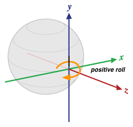
Figura 3. Orientación relativa a un dispositivo
Esta definición es diferente de la guiñada, el cabeceo y el alabeo utilizados en la aviación, donde el eje X se encuentra a lo largo del lado largo del avión (de cola a morro).
El sensor de orientación también informa qué tan precisa espera que sean sus lecturas a través de sensors_event_t.orientation.status . Consulte las SensorManager SENSOR_STATUS_* de SensorManager para obtener más información sobre los valores posibles para este campo.
Sensores no calibrados
Los sensores no calibrados brindan más resultados sin procesar y pueden incluir algunos sesgos, pero también contienen menos "saltos" de las correcciones aplicadas a través de la calibración. Algunas aplicaciones pueden preferir estos resultados no calibrados como más fluidos y confiables. Por ejemplo, si una aplicación intenta realizar su propia fusión de sensores, la introducción de calibraciones puede distorsionar los resultados.
Acelerómetro sin calibrar
Sensor físico subyacente: Acelerómetro
Modo de informe: continuo
getDefaultSensor(SENSOR_TYPE_ACCELEROMETER_UNCALIBRATED) devuelve un sensor que no es de activación
Un sensor de acelerómetro no calibrado informa la aceleración del dispositivo a lo largo de los tres ejes del sensor sin ninguna corrección de sesgo (el sesgo de fábrica y la compensación de temperatura se aplican a las mediciones no calibradas), junto con una estimación del sesgo. Todos los valores están en unidades SI (m/s^2) y se informan en los campos de sensors_event_t.uncalibrated_accelerometer :
-
x_uncalib: aceleración (sin compensación de polarización) a lo largo del eje X -
y_uncalib: aceleración (sin compensación de polarización) a lo largo del eje Y -
z_uncalib: aceleración (sin compensación de polarización) a lo largo del eje Z -
x_bias: sesgo estimado a lo largo del eje X -
y_bias: sesgo estimado a lo largo del eje Y -
z_bias: sesgo estimado a lo largo del eje Z
Giroscopio sin calibrar
Sensor físico subyacente: giroscopio
Modo de informe: continuo
getDefaultSensor(SENSOR_TYPE_GYROSCOPE_UNCALIBRATED) devuelve un sensor que no es de activación
Un giroscopio no calibrado informa la velocidad de rotación alrededor de los ejes del sensor sin aplicarles una compensación de sesgo, junto con una estimación del sesgo. Todos los valores están en radianes/segundo y se informan en los campos de sensors_event_t.uncalibrated_gyro :
-
x_uncalib: velocidad angular (sin compensación de deriva) alrededor del eje X -
y_uncalib: velocidad angular (sin compensación de deriva) alrededor del eje Y -
z_uncalib: velocidad angular (sin compensación de deriva) alrededor del eje Z -
x_bias: deriva estimada alrededor del eje X -
y_bias: deriva estimada alrededor del eje Y -
z_bias: deriva estimada alrededor del eje Z
Conceptualmente, la medida no calibrada es la suma de la medida calibrada y la estimación del sesgo: _uncalibrated = _calibrated + _bias .
Se espera que los valores de x_bias , y_bias y z_bias salten tan pronto como cambie la estimación del sesgo, y deberían permanecer estables el resto del tiempo.
Consulte la definición del sensor de giroscopio para obtener detalles sobre el sistema de coordenadas utilizado.
Se debe aplicar la calibración de fábrica y la compensación de temperatura a las mediciones. Además, se debe implementar la estimación de deriva del giroscopio para que se puedan informar estimaciones razonables en x_bias , y_bias y z_bias . Si la implementación no puede estimar la deriva, entonces este sensor no debe implementarse.
Si este sensor está presente, entonces el sensor de giroscopio correspondiente también debe estar presente y ambos sensores deben compartir los mismos valores sensor_t.name y sensor_t.vendor .
Campo magnético sin calibrar
Sensor físico subyacente: Magnetómetro
Modo de informe: continuo
getDefaultSensor(SENSOR_TYPE_MAGNETIC_FIELD_UNCALIBRATED) devuelve un sensor que no es de activación
Un sensor de campo magnético no calibrado informa el campo magnético ambiental junto con una estimación de calibración de hierro duro. Todos los valores están en micro-Tesla (uT) y se informan en los campos de sensors_event_t.uncalibrated_magnetic :
-
x_uncalib: campo magnético (sin compensación de hierro duro) a lo largo del eje X -
y_uncalib: campo magnético (sin compensación de hierro duro) a lo largo del eje Y -
z_uncalib: campo magnético (sin compensación de hierro duro) a lo largo del eje Z -
x_bias: sesgo de hierro duro estimado a lo largo del eje X -
y_bias: sesgo de hierro duro estimado a lo largo del eje Y -
z_bias: sesgo de hierro duro estimado a lo largo del eje Z
Conceptualmente, la medida no calibrada es la suma de la medida calibrada y la estimación del sesgo: _uncalibrated = _calibrated + _bias .
El magnetómetro no calibrado permite que los algoritmos de nivel superior manejen una mala estimación de hierro duro. Se espera que los valores de x_bias , y_bias y z_bias salten tan pronto como cambie la estimación del hierro duro, y deberían permanecer estables el resto del tiempo.
Se debe aplicar calibración de hierro dulce y compensación de temperatura a las mediciones. Además, se debe implementar una estimación de hierro duro para que se puedan informar estimaciones razonables en x_bias , y_bias y z_bias . Si la implementación no puede estimar el sesgo, entonces este sensor no debe implementarse.
Si este sensor está presente, entonces el sensor de campo magnético correspondiente debe estar presente y ambos sensores deben compartir los mismos valores sensor_t.name y sensor_t.vendor .
Ángulo de bisagra
Modo de informe: Al cambiar
getDefaultSensor(SENSOR_TYPE_HINGE_ANGLE) devuelve un sensor de activación
Un sensor de ángulo de bisagra mide el ángulo, en grados, entre dos partes integrales del dispositivo. Se espera que el movimiento de una bisagra medido por este tipo de sensor altere las formas en que el usuario puede interactuar con el dispositivo, por ejemplo, al desplegar o revelar una pantalla.
Sensores compuestos de interacción
Algunos sensores se utilizan principalmente para detectar interacciones con el usuario. We don't define how those sensors must be implemented, but they must be low power and it's the responsibility of the device manufacturer to verify their quality in terms of user experience.
Wake up gesture
Underlying physical sensors: Undefined (anything low power)
Reporting-mode: One-shot
Low-power
Implement only the wake-up version of this sensor.
getDefaultSensor(SENSOR_TYPE_WAKE_GESTURE) returns a wake-up sensor
A wake up gesture sensor enables waking up the device based on a device specific motion. When this sensor triggers, the device behaves as if the power button was pressed, turning the screen on. This behavior (turning on the screen when this sensor triggers) might be deactivated by the user in the device settings. Changes in settings don't impact the behavior of the sensor: only whether the framework turns the screen on when it triggers. The actual gesture to be detected isn't specified, and can be chosen by the manufacturer of the device.
This sensor must be low power, as it's likely to be activated 24/7.
Each sensor event reports 1 in sensors_event_t.data[0] .
Pick up gesture
Underlying physical sensors: Undefined (anything low power)
Reporting-mode: One-shot
Low-power
Implement only the wake-up version of this sensor.
getDefaultSensor(SENSOR_TYPE_PICK_UP_GESTURE) returns a wake-up sensor
A pick-up gesture sensor triggers when the device is picked up regardless of wherever it was before (desk, pocket, bag).
Each sensor event reports 1 in sensors_event_t.data[0] .
Glance gesture
Underlying physical sensors: Undefined (anything low power)
Reporting-mode: One-shot
Low-power
Implement only the wake-up version of this sensor.
getDefaultSensor(SENSOR_TYPE_GLANCE_GESTURE) returns a wake-up sensor
A glance gesture sensor enables briefly turning the screen on to enable the user to glance content on screen based on a specific motion. When this sensor triggers, the device will turn the screen on momentarily to allow the user to glance notifications or other content while the device remains locked in a non-interactive state (dozing), then the screen will turn off again. This behavior (briefly turning on the screen when this sensor triggers) might be deactivated by the user in the device settings. Changes in settings do not impact the behavior of the sensor: only whether the framework briefly turns the screen on when it triggers. The actual gesture to be detected isn't specified, and can be chosen by the manufacturer of the device.
This sensor must be low power, as it's likely to be activated 24/7. Each sensor event reports 1 in sensors_event_t.data[0] .
Limited axes IMU sensors
Available from Android 13, limited axes IMU sensors are sensors that support use cases where not all three axes (x, y, z) are available. Standard IMU types in Android (such as SENSOR_TYPE_ACCELEROMETER and SENSOR_TYPE_GYROSCOPE ) assume that all three axes are supported. However, not all form factors and devices support 3-axis accelerometers and 3-axis gyroscopes.
Accelerometer limited axes
Underlying physical sensors: Accelerometer
Reporting-mode: Continuous
getDefaultSensor(SENSOR_TYPE_ACCELEROMETER_LIMITED_AXES) returns a non-wake-up sensor
An accelerometer limited axes sensor is equivalent to TYPE_ACCELEROMETER but supports cases where one or two axes aren't supported.
The last three sensor event values reported by the sensor represent whether the acceleration value for the x, y, and z axes are supported. A value of 1.0 indicates that the axis is supported, and a value of 0 indicates it isn't supported. Device manufacturers identify the supported axes at build time and the values don't change during runtime.
Device manufacturers must set the acceleration values for unused axes to 0 , instead of having undefined values.
Gyroscope limited axes
Underlying physical sensors: Gyroscope
Reporting-mode: Continuous
getDefaultSensor(SENSOR_TYPE_GYROSCOPE_LIMITED_AXES) returns a non-wake-up sensor
A gyroscope limited axes sensor is equivalent to TYPE_GYROSCOPE but supports cases where one or two axes aren't supported.
The last three sensor event values reported by the sensor represent whether the angular speed value for the x, y, and z axes are supported. A value of 1.0 indicates that the axis is supported, and a value of 0 indicates it isn't supported. Device manufacturers identify the supported axes at build time and the values don't change during runtime.
Device manufacturers must set the angular speed values for unused axes to 0 .
Accelerometer limited axes uncalibrated
Underlying physical sensors: Accelerometer
Reporting-mode: Continuous
getDefaultSensor(SENSOR_TYPE_ACCELEROMETER_LIMITED_AXES_UNCALIBRATED) returns a non-wake-up sensor
An accelerometer limited axes uncalibrated sensor is equivalent to TYPE_ACCELEROMETER_UNCALIBRATED but supports cases where one or two axes aren't supported.
The last three sensor event values reported by the sensor represent whether the acceleration and bias values for the x, y, and z axes are supported. A value of 1.0 indicates that the axis is supported, and a value of 0 indicates it isn't supported. Device manufacturers identify the supported axes at build time and the values don't change during runtime.
Device manufacturers must set the acceleration and bias values for unused axes to 0 .
Gyroscope limited axes uncalibrated
Underlying physical sensors: Gyroscope
Reporting-mode: Continuous
getDefaultSensor(SENSOR_TYPE_GYROSCOPE_LIMITED_AXES_UNCALIBRATED) returns a non-wake-up sensor
A gyroscope limited axes uncalibrated sensor is equivalent to TYPE_GYROSCOPE_UNCALIBRATED but supports cases where one or two axes aren't supported.
The last three sensor event values reported by the sensor represent whether the angular speed and drift values for the x, y, and z axes are supported. A value of 1.0 indicates that the axis is supported, and a value of 0 indicates it isn't supported. Device manufacturers identify the supported axes at build time and the values don't change during runtime.
Device manufacturers must set the angular speed and drift values for unused axes to 0 .
Composite limited axes IMU
Underlying physical sensors: Any combination of 3-axis accelerometer, 3-axis gyroscope, 3-axis accelerometer uncalibrated, and 3-axis gyroscope uncalibrated sensors.
Reporting-mode: Continuous
A composite limited axes IMU sensor is equivalent to a limited axes IMU sensor but instead of being supported at the HAL, it converts the 3-axis sensor data into the equivalent limited axes variants. These composite sensors are only enabled for automotive devices.
The following table shows an example conversion from a standard 3-axis accelerometer to a composite limited axes accelerometer.
| SensorEvent Values for SENSOR_TYPE_ACCELEROMETER | Example SENSOR_TYPE_ACCELEROMETER SensorEvent | Composite SENSOR_TYPE_ACCELEROMETER_LIMITED_AXES SensorEvent |
|---|---|---|
| values[0] | -0.065 | -0.065 |
| values[1] | 0.078 | 0.078 |
| values[2] | 9.808 | 9.808 |
| values[3] | N / A | 1.0 |
| values[4] | N / A | 1.0 |
| values[5] | N / A | 1.0 |
Automotive sensors
Sensors to support automotive use cases.
Heading
Underlying physical sensors: Any combination of GPS, magnetometer, accelerometer, and gyroscope.
Reporting-mode: Continuous
getDefaultSensor(SENSOR_TYPE_HEADING) returns a non-wake-up sensor
Available from Android 13, a heading sensor measures the direction in which the device is pointing relative to true north in degrees. The heading sensor includes two SensorEvent values. One for the measured device heading and one for the accuracy of the provided heading value.
Heading values reported by this sensor must be between 0.0 (inclusive) and 360.0 (exclusive), with 0 indicating north, 90 east, 180 south, and 270 west.
Accuracy for this sensor is defined at 68 percent confidence. In the case where the underlying distribution is Gaussian normal, the accuracy is one standard deviation. For example, if the heading sensor returns a heading value of 60 degrees and an accuracy value of 10 degrees, there's a 68 percent probability of the true heading being between 50 degrees and 70 degrees.
,This section describes sensor axes, base sensors, and composite sensors (activity, attitude, uncalibrated, and interaction).
Sensor axes
Sensor event values from many sensors are expressed in a specific frame that is static relative to the device.
Mobile device axes
The Sensor API is relative only to the natural orientation of the screen (axes aren't swapped when the device's screen orientation changes.
Figure 1. Coordinate system (relative to a mobile device) used by the Sensor API
Automotive axes
In Android Automotive implementations, axes are defined with respect to the vehicle body frame. The origin of the vehicle reference frame is the center of the rear axle. The vehicle reference frame is oriented so that the:
- X-axis points to the right and is on a horizontal plane, perpendicular to the vehicle plane of symmetry.
- Y-axis points forward and is on a horizontal plane.
Figure 2. Coordinate system (relative to an automotive device) used by the Sensor API
The vehicle reference frame is a right-handed coordinate system. Therefore, the Z-axis points up.
The Z-axis of the reference frame is aligned to gravity, which means that the X-axis and Y-axis are both horizontal. As a result, the Y-axis may not always go through the front axle.
Base sensors
Base sensor types are named after the physical sensors they represent. These sensors relay data from a single physical sensor (as opposed to composite sensors that generate data out of other sensors). Examples of base sensor types include:
-
SENSOR_TYPE_ACCELEROMETER -
SENSOR_TYPE_GYROSCOPE -
SENSOR_TYPE_MAGNETOMETER
However, base sensors aren't equal to and shouldn't be confused with their underlying physical sensor. The data from a base sensor is not the raw output of the physical sensor because corrections (such as bias compensation and temperature compensation) are applied.
For example, the characteristics of a base sensor might be different from the characteristics of its underlying physical sensor in the following use cases:
- A gyroscope chip rated to have a bias range of 1 deg/sec.
- After factory calibration, temperature compensation and bias compensation are applied, the actual bias of the Android sensor will be reduced, may be to a point where the bias is guaranteed to be below 0.01 deg/sec.
- In this situation, we say that the Android sensor has a bias below 0.01 deg/sec, even though the data sheet of the underlying sensor said 1 deg/sec.
- A barometer with a power consumption of 100 uW.
- Because the generated data needs to be transported from the chip to the SoC, the actual power cost to gather data from the barometer Android sensor might be much higher, for example 1000 uW.
- In this situation, we say that the Android sensor has a power consumption of 1000 uW, even though the power consumption measured at the barometer chip leads is 100uW.
- A magnetometer that consumes 100uW when calibrated, but consumes more when calibrating.
- Its calibration routine might require activating the gyroscope, consuming 5000 uW, and running some algorithm, costing another 900 uW.
- In this situation, we say that the maximum power consumption of the (magnetometer) Android sensor is 6000 uW.
- In this case, the average power consumption is the more useful measure, and it's what is reported in the sensor static characteristics through the HAL.
Accelerometer
Reporting-mode: Continuous
getDefaultSensor(SENSOR_TYPE_ACCELEROMETER) returns a non-wake-up sensor
An accelerometer sensor reports the acceleration of the device along the three sensor axes. The measured acceleration includes both the physical acceleration (change of velocity) and the gravity. The measurement is reported in the x, y, and z fields of sensors_event_t.acceleration.
All values are in SI units (m/s^2) and measure the acceleration of the device minus the force of gravity along the three sensor axes.
Here are examples:
- The norm of (x, y, z) should be close to 0 when in free fall.
- When the device lies flat on a table and is pushed on its left side toward the right, the x acceleration value is positive.
- When the device lies flat on a table, the acceleration value along z is +9.81 alo, which corresponds to the acceleration of the device (0 m/s^2) minus the force of gravity (-9.81 m/s^2).
- When the device lies flat on a table and is pushed toward the sky, the acceleration value is greater than +9.81, which corresponds to the acceleration of the device (+A m/s^2) minus the force of gravity (-9.81 m/s^2).
The readings are calibrated using:
- Temperature compensation
- Online bias calibration
- Online scale calibration
The bias and scale calibration must only be updated while the sensor is deactivated, so as to avoid causing jumps in values during streaming.
The accelerometer also reports how accurate it expects its readings to be through sensors_event_t.acceleration.status . See the SensorManager 's SENSOR_STATUS_* constants for more information on possible values for this field.
Ambient temperature
Reporting-mode: On-change
getDefaultSensor(SENSOR_TYPE_AMBIENT_TEMPERATURE) returns a non-wake-up sensor
This sensor provides the ambient (room) temperature in degrees Celsius.
Magnetic field sensor
Reporting-mode: Continuous
getDefaultSensor(SENSOR_TYPE_MAGNETIC_FIELD) returns a non-wake-up sensor
SENSOR_TYPE_GEOMAGNETIC_FIELD == SENSOR_TYPE_MAGNETIC_FIELD
A magnetic field sensor (also known as magnetometer) reports the ambient magnetic field, as measured along the three sensor axes.
The measurement is reported in the x, y, and z fields of sensors_event_t.magnetic and all values are in micro-Tesla (uT).
The magnetometer also reports how accurate it expects its readings to be through sensors_event_t.magnetic.status . See the SensorManager 's SENSOR_STATUS_* constants for more information on possible values for this field.
The readings are calibrated using:
- Temperature compensation
- Factory (or online) soft-iron calibration
- Online hard-iron calibration
Gyroscope
Reporting-mode: Continuous
getDefaultSensor(SENSOR_TYPE_GYROSCOPE) returns a non-wake-up sensor
A gyroscope sensor reports the rate of rotation of the device around the three sensor axes.
Rotation is positive in the counterclockwise direction (right-hand rule). That is, an observer looking from some positive location on the x, y, or z axis at a device positioned on the origin would report positive rotation if the device appeared to be rotating counter clockwise. Note that this is the standard mathematical definition of positive rotation and does not agree with the aerospace definition of roll.
The measurement is reported in the x, y, and z fields of sensors_event_t.gyro and all values are in radians per second (rad/s).
The readings are calibrated using:
- Temperature compensation
- Factory (or online) scale compensation
- Online bias calibration (to remove drift)
The gyroscope also reports how accurate it expects its readings to be through sensors_event_t.gyro.status . See the SensorManager 's SENSOR_STATUS_* constants for more information on possible values for this field.
The gyroscope can't be emulated based on magnetometers and accelerometers, as this would cause it to have reduced local consistency and responsiveness. It must be based on a usual gyroscope chip.
Heart Rate
Reporting-mode: On-change
getDefaultSensor(SENSOR_TYPE_HEART_RATE) returns a non-wake-up sensor
A heart rate sensor reports the current heart rate of the person touching the device.
The current heart rate in beats per minute (BPM) is reported in sensors_event_t.heart_rate.bpm and the status of the sensor is reported in sensors_event_t.heart_rate.status . See the SensorManager 's SENSOR_STATUS_* constants for more information on possible values for this field. In particular, upon the first activation, unless the device is known to not be on the body, the status field of the first event must be set to SENSOR_STATUS_UNRELIABLE . Because this sensor is on-change, events are generated when and only when heart_rate.bpm or heart_rate.status have changed since the last event. The events are generated no faster than every sampling_period .
sensor_t.requiredPermission is always SENSOR_PERMISSION_BODY_SENSORS .
Light
Reporting-mode: On-change
getDefaultSensor(SENSOR_TYPE_LIGHT) returns a non-wake-up sensor
A light sensor reports the current illumination in SI lux units.
The measurement is reported in sensors_event_t.light .
Proximity
Reporting-mode: On-change
Usually defined as a wake-up sensor
getDefaultSensor(SENSOR_TYPE_PROXIMITY) returns a wake-up sensor
A proximity sensor reports the distance from the sensor to the closest visible surface.
Up to Android 4.4, the proximity sensors were always wake-up sensors, waking up the SoC when detecting a change in proximity. After Android 4.4, we advise to implement the wake-up version of this sensor first, as it's the one that is used to turn the screen on and off while making phone calls.
The measurement is reported in centimeters in sensors_event_t.distance . Note that some proximity sensors only support a binary "near" or "far" measurement. In this case, the sensor report its sensor_t.maxRange value in the "far" state and a value less than sensor_t.maxRange in the "near" state.
Pressure
Reporting-mode: Continuous
getDefaultSensor(SENSOR_TYPE_PRESSURE) returns a non-wake-up sensor
A pressure sensor (also known as barometer) reports the atmospheric pressure in hectopascal (hPa).
The readings are calibrated using
- Temperature compensation
- Factory bias calibration
- Factory scale calibration
The barometer is often used to estimate elevation changes. To estimate absolute elevation, the sea-level pressure (changing depending on the weather) must be used as a reference.
Relative humidity
Reporting-mode: On-change
getDefaultSensor(SENSOR_TYPE_RELATIVE_HUMIDITY) returns a non-wake-up sensor
A relative humidity sensor measures relative ambient air humidity and returns a value in percent.
Composite sensor types
A composite sensor generates data by processing and/or fusing data from one or several physical sensors. (Any sensor that isn't a base sensor is called a composite sensor.) Examples of composite sensors include:
- Step detector and significant motion , which are usually based on an accelerometer, but could be based on other sensors as well, if the power consumption and accuracy was acceptable.
- Game rotation vector , based on an accelerometer and a gyroscope.
- Uncalibrated gyroscope , which is similar to the gyroscope base sensor, but with the bias calibration being reported separately instead of being corrected in the measurement.
As with base sensors, the characteristics of the composite sensors come from the characteristics of their final data. For example, the power consumption of a game rotation vector is probably equal to the sum of the power consumptions of the accelerometer chip, the gyroscope chip, the chip processing the data, and the buses transporting the data. As another example, the drift of a game rotation vector depends as much on the quality of the calibration algorithm as on the physical sensor characteristics.
The following table lists available composite sensor types. Each composite sensor relies on data from one or several physical sensors. Avoid choosing other underlying physical sensors to approximate results as they provide a poor user experience.
| Sensor type | Category | Underlying physical sensors | Reporting mode |
|---|---|---|---|
Attitude | Accelerometer, gyroscope, MUST NOT USE magnetometer | Continuous | |
Attitude | Accelerometer, magnetometer, MUST NOT USE gyroscope | Continuous | |
| Glance gesture | Interaction | Undefined | One-shot |
Attitude | Accelerometer, gyroscope | Continuous | |
Uncalibrated | Gyroscope | Continuous | |
Activity | Accelerometer, gyroscope (if present), or magnetometer (if gyro not present) | Continuous | |
Uncalibrated | Magnetometer | Continuous | |
Orientation (deprecated) | Attitude | Accelerometer, magnetometer, gyroscope (if present) | Continuous |
Interaction | Undefined | One-shot | |
Attitude | Accelerometer, magnetometer, gyroscope | Continuous | |
Activity | Accelerometer (or another as long as very low power) | One-shot | |
Activity | Accelerometer | On-change | |
Activity | Accelerometer | Special | |
Activity | Accelerometer | Special | |
Interaction | Undefined | One-shot |
![]() = Low power sensor
= Low power sensor
Activity composite sensors
Linear acceleration
Underlying physical sensors: Accelerometer and (if present) gyroscope (or magnetometer if gyroscope not present)
Reporting-mode: Continuous
getDefaultSensor(SENSOR_TYPE_LINEAR_ACCELERATION) returns a non-wake-up sensor
A linear acceleration sensor reports the linear acceleration of the device in the sensor frame, not including gravity.
The output is conceptually: output of the accelerometer minus the output of the gravity sensor . It's reported in m/s^2 in the x, y, and z fields of sensors_event_t.acceleration .
Readings on all axes should be close to 0 when the device is immobile.
If the device possesses a gyroscope, the linear acceleration sensor must use the gyroscope and accelerometer as input.
If the device doesn't possess a gyroscope, the linear acceleration sensor must use the accelerometer and the magnetometer as input.
Significant motion
Underlying physical sensor: Accelerometer (or another as long as low power)
Reporting-mode: One-shot
Low power
Implement only the wake-up version of this sensor.
getDefaultSensor(SENSOR_TYPE_SIGNIFICANT_MOTION) returns a wake-up sensor
A significant motion detector triggers when detecting a significant motion : a motion that might lead to a change in the user location.
Examples of such significant motions are:
- Walking or biking
- Sitting in a moving car, coach, or train
Examples of situations that don't trigger significant motion:
- Phone in pocket and person isn't moving
- Phone is on a table and the table shakes a bit due to nearby traffic or washing machine
At the high level, the significant motion detector is used to reduce the power consumption of location determination. When the localization algorithms detect that the device is static, they can switch to a low-power mode, where they rely on significant motion to wake the device up when the user is changing location.
This sensor must be low power. It makes a tradeoff for power consumption that may result in a small amount of false negatives. This is done for a few reasons:
- The goal of this sensor is to save power.
- Triggering an event when the user isn't moving (false positive) is costly in terms of power, so it should be avoided.
- Not triggering an event when the user is moving (false negative) is acceptable as long as it isn't done repeatedly. If the user has been walking for 10 seconds, not triggering an event within those 10 seconds isn't acceptable.
Each sensor event reports 1 in sensors_event_t.data[0] .
Step detector
Underlying physical sensor: Accelerometer (+ possibly others as long as low power)
Reporting-mode: Special (one event per step taken)
Low power
getDefaultSensor(SENSOR_TYPE_STEP_DETECTOR) returns a non-wake-up sensor
A step detector generates an event each time a step is taken by the user.
The timestamp of the event sensors_event_t.timestamp corresponds to when the foot hit the ground, generating a high variation in acceleration.
Compared to the step counter, the step detector should have a lower latency (less than two seconds). Both the step detector and the step counter detect when the user is walking, running, and walking up the stairs. They shouldn't trigger when the user is biking, driving, or in other vehicles.
This sensor must be low power. That is, if the step detection cannot be done in hardware, this sensor shouldn't be defined. In particular, when the step detector is activated and the accelerometer isn't, only steps should trigger interrupts (not every accelerometer reading).
sampling_period_ns has no impact on step detectors.
Each sensor event reports 1 in sensors_event_t.data[0] .
Step counter
Underlying physical sensor: Accelerometer (+ possibly others as long as low power)
Reporting-mode: On-change
Low-power
getDefaultSensor(SENSOR_TYPE_STEP_COUNTER) returns a non-wake-up sensor
A step counter reports the number of steps taken by the user since the last reboot while activated.
The measurement is reported as a uint64_t in sensors_event_t.step_counter and is reset to zero only on a system reboot.
The timestamp of the event is set to the time when the last step for that event was taken.
See the Step detector sensor type for the signification of the time of a step.
Compared to the step detector, the step counter can have a higher latency (up to 10 seconds). Thanks to this latency, this sensor has a high accuracy; the step count after a full day of measures should be within 10% of the actual step count. Both the step detector and the step counter detect when the user is walking, running, and walking up the stairs. They shouldn't trigger when the user is biking, driving, or in other vehicles.
The hardware must ensure the internal step count never overflows. The minimum size of the hardware's internal counter shall be 16 bits. In case of imminent overflow (at most every ~2^16 steps), the SoC can be woken up so the driver can do the counter maintenance.
As stated in Interaction , while this sensor operates, it shall not disrupt any other sensors, in particular, the accelerometer, which might very well be in use.
If a particular device can't support these modes of operation, then this sensor type must not be reported by the HAL. That is, it isn't acceptable to "emulate" this sensor in the HAL.
This sensor must be low power. That is, if the step detection can't be done in hardware, this sensor shouldn't be defined. In particular, when the step counter is activated and the accelerometer isn't, only steps should trigger interrupts (not accelerometer data).
Tilt detector
Underlying physical sensor: Accelerometer (+ possibly others as long as low power)
Reporting-mode: Special
Low-power
Implement only the wake-up version of this sensor.
getDefaultSensor(SENSOR_TYPE_TILT_DETECTOR) returns a wake-up sensor
A tilt detector generates an event each time a tilt event is detected.
A tilt event is defined by the direction of the 2-seconds window average gravity changing by at least 35 degrees since the activation or the last event generated by the sensor. Here is the algorithm:
-
reference_estimated_gravity= average of accelerometer measurements over the first second after activation or the estimated gravity when the last tilt event was generated. -
current_estimated_gravity= average of accelerometer measurements over the last 2 seconds. - Trigger when
angle(reference_estimated_gravity, current_estimated_gravity) > 35 degrees
Large accelerations without a change in phone orientation shouldn't trigger a tilt event. For example, a sharp turn or strong acceleration while driving a car shouldn't trigger a tilt event, even though the angle of the average acceleration might vary by more than 35 degrees. Typically, this sensor is implemented with the help of only an accelerometer. Other sensors can be used as well if they do not increase the power consumption significantly. This is a low-power sensor that should allow the SoC to go into suspend mode. Do not emulate this sensor in the HAL. Each sensor event reports 1 in sensors_event_t.data[0] .
Attitude composite sensors
Rotation vector
Underlying physical sensors: Accelerometer, magnetometer, and gyroscope
Reporting-mode: Continuous
getDefaultSensor(SENSOR_TYPE_ROTATION_VECTOR) returns a non-wake-up sensor
A rotation vector sensor reports the orientation of the device relative to the East-North-Up coordinates frame. It's usually obtained by integration of accelerometer, gyroscope, and magnetometer readings. The East-North-Up coordinate system is defined as a direct orthonormal basis where:
- X points east and is tangential to the ground.
- Y points north and is tangential to the ground.
- Z points towards the sky and is perpendicular to the ground.
The orientation of the phone is represented by the rotation necessary to align the East-North-Up coordinates with the phone's coordinates. That is, applying the rotation to the world frame (X,Y,Z) would align them with the phone coordinates (x,y,z).
The rotation can be seen as rotating the phone by an angle theta around an axis rot_axis to go from the reference (East-North-Up aligned) device orientation to the current device orientation. The rotation is encoded as the four unit-less x, y, z, w components of a unit quaternion:
-
sensors_event_t.data[0] = rot_axis.x*sin(theta/2) -
sensors_event_t.data[1] = rot_axis.y*sin(theta/2) -
sensors_event_t.data[2] = rot_axis.z*sin(theta/2) -
sensors_event_t.data[3] = cos(theta/2)
Where:
- The x, y, and z fields of
rot_axisare the East-North-Up coordinates of a unit length vector representing the rotation axis -
thetais the rotation angle
The quaternion is a unit quaternion: It must be of norm 1 . Failure to ensure this will cause erratic client behavior.
In addition, this sensor reports an estimated heading accuracy:
sensors_event_t.data[4] = estimated_accuracy (in radians)
The heading error must be less than estimated_accuracy 95% of the time. This sensor must use a gyroscope as the main orientation change input.
This sensor also uses accelerometer and magnetometer input to make up for gyroscope drift, and it can't be implemented using only the accelerometer and magnetometer.
Game rotation vector
Underlying physical sensors: Accelerometer and gyroscope (no magnetometer)
Reporting-mode: Continuous
getDefaultSensor(SENSOR_TYPE_GAME_ROTATION_VECTOR) returns a non-wake-up sensor
A game rotation vector sensor is similar to a rotation vector sensor but not using the geomagnetic field. Therefore the Y axis doesn't point north but instead to some other reference. That reference is allowed to drift by the same order of magnitude as the gyroscope drifts around the Z axis.
See the Rotation vector sensor for details on how to set sensors_event_t.data[0-3] . This sensor doesn't report an estimated heading accuracy: sensors_event_t.data[4] is reserved and should be set to 0 .
In an ideal case, a phone rotated and returned to the same real-world orientation should report the same game rotation vector.
This sensor must be based on a gyroscope and an accelerometer. It can't use magnetometer as an input, besides, indirectly, through estimation of the gyroscope bias.
Gravity
Underlying physical sensors: Accelerometer and (if present) gyroscope (or magnetometer if gyroscope not present)
Reporting-mode: Continuous
getDefaultSensor(SENSOR_TYPE_GRAVITY) returns a non-wake-up sensor
A gravity sensor reports the direction and magnitude of gravity in the device's coordinates.
The gravity vector components are reported in m/s^2 in the x, y, and z fields of sensors_event_t.acceleration .
When the device is at rest, the output of the gravity sensor should be identical to that of the accelerometer. On Earth, the magnitude is around 9.8 m/s^2.
If the device possesses a gyroscope, the gravity sensor must use the gyroscope and accelerometer as input.
If the device doesn't possess a gyroscope, the gravity sensor must use the accelerometer and the magnetometer as input.
Geomagnetic rotation vector
Underlying physical sensors: Accelerometer and magnetometer (no gyroscope)
Reporting-mode: Continuous
Low-power
getDefaultSensor(SENSOR_TYPE_GEOMAGNETIC_ROTATION_VECTOR) returns a non-wake-up sensor
A geomagnetic rotation vector is similar to a rotation vector sensor but using a magnetometer and no gyroscope.
This sensor must be based on a magnetometer. It can't be implemented using a gyroscope, and gyroscope input can't be used by this sensor.
See the Rotation vector sensor for details on how to set sensors_event_t.data[0-4] .
Just like for the rotation vector sensor, the heading error must be less than the estimated accuracy ( sensors_event_t.data[4] ) 95% of the time.
This sensor must be low power, so it has to be implemented in hardware.
Orientation (deprecated)
Underlying physical sensors: Accelerometer, magnetometer and (if present) gyroscope
Reporting-mode: Continuous
getDefaultSensor(SENSOR_TYPE_ORIENTATION) returns a non-wake-up sensor
Note: This is an older sensor type that has been deprecated in the Android SDK. It has been replaced by the rotation vector sensor, which is more clearly defined. Use the rotation vector sensor over the orientation sensor whenever possible.
An orientation sensor reports the attitude of the device. The measurements are reported in degrees in the x, y, and z fields of sensors_event_t.orientation :
-
sensors_event_t.orientation.x: azimuth, the angle between the magnetic north direction and the Y axis, around the Z axis (0<=azimuth<360). 0=North, 90=East, 180=South, 270=West. -
sensors_event_t.orientation.y: pitch, rotation around X axis (-180<=pitch<=180), with positive values when the Z axis moves toward the Y axis. -
sensors_event_t.orientation.z: roll, rotation around Y axis (-90<=roll<=90), with positive values when the X axis moves towards the Z axis.
Please note, for historical reasons the roll angle is positive in the clockwise direction. (Mathematically speaking, it should be positive in the counter-clockwise direction):
Figure 3. Orientation relative to a device
This definition is different from yaw, pitch, and roll used in aviation where the X axis is along the long side of the plane (tail to nose).
The orientation sensor also reports how accurate it expects its readings to be through sensors_event_t.orientation.status . See the SensorManager 's SENSOR_STATUS_* constants for more information on possible values for this field.
Uncalibrated sensors
Uncalibrated sensors provide more raw results and may include some bias but also contain fewer "jumps" from corrections applied through calibration. Some apps may prefer these uncalibrated results as smoother and more reliable. For instance, if an app is attempting to conduct its own sensor fusion, introducing calibrations can actually distort results.
Accelerometer uncalibrated
Underlying physical sensor: Accelerometer
Reporting-mode: Continuous
getDefaultSensor(SENSOR_TYPE_ACCELEROMETER_UNCALIBRATED) returns a non-wake-up sensor
An uncalibrated accelerometer sensor reports the acceleration of the device along the three sensor axes without any bias correction (factory bias and temperature compensation are applied to uncalibrated measurements), along with a bias estimate. All values are in SI units (m/s^2) and are reported in the fields of sensors_event_t.uncalibrated_accelerometer :
-
x_uncalib: acceleration (without bias compensation) along the X axis -
y_uncalib: acceleration (without bias compensation) along the Y axis -
z_uncalib: acceleration (without bias compensation) along the Z axis -
x_bias: estimated bias along X axis -
y_bias: estimated bias along Y axis -
z_bias: estimated bias along Z axis
Gyroscope uncalibrated
Underlying physical sensor: Gyroscope
Reporting-mode: Continuous
getDefaultSensor(SENSOR_TYPE_GYROSCOPE_UNCALIBRATED) returns a non-wake-up sensor
An uncalibrated gyroscope reports the rate of rotation around the sensor axes without applying bias compensation to them, along with a bias estimate. All values are in radians/second and are reported in the fields of sensors_event_t.uncalibrated_gyro :
-
x_uncalib: angular speed (without drift compensation) around the X axis -
y_uncalib: angular speed (without drift compensation) around the Y axis -
z_uncalib: angular speed (without drift compensation) around the Z axis -
x_bias: estimated drift around X axis -
y_bias: estimated drift around Y axis -
z_bias: estimated drift around Z axis
Conceptually, the uncalibrated measurement is the sum of the calibrated measurement and the bias estimate: _uncalibrated = _calibrated + _bias .
The x_bias , y_bias and z_bias values are expected to jump as soon as the estimate of the bias changes, and they should be stable the rest of the time.
See the definition of the gyroscope sensor for details on the coordinate system used.
Factory calibration and temperature compensation must be applied to the measurements. Also, gyroscope drift estimation must be implemented so that reasonable estimates can be reported in x_bias , y_bias and z_bias . If the implementation isn't able to estimate the drift, then this sensor must not be implemented.
If this sensor is present, then the corresponding Gyroscope sensor must also be present and both sensors must share the same sensor_t.name and sensor_t.vendor values.
Magnetic field uncalibrated
Underlying physical sensor: Magnetometer
Reporting-mode: Continuous
getDefaultSensor(SENSOR_TYPE_MAGNETIC_FIELD_UNCALIBRATED) returns a non-wake-up sensor
An uncalibrated magnetic field sensor reports the ambient magnetic field together with a hard iron calibration estimate. All values are in micro-Tesla (uT) and are reported in the fields of sensors_event_t.uncalibrated_magnetic :
-
x_uncalib: magnetic field (without hard-iron compensation) along the X axis -
y_uncalib: magnetic field (without hard-iron compensation) along the Y axis -
z_uncalib: magnetic field (without hard-iron compensation) along the Z axis -
x_bias: estimated hard-iron bias along the X axis -
y_bias: estimated hard-iron bias along the Y axis -
z_bias: estimated hard-iron bias along the Z axis
Conceptually, the uncalibrated measurement is the sum of the calibrated measurement and the bias estimate: _uncalibrated = _calibrated + _bias .
The uncalibrated magnetometer allows higher level algorithms to handle bad hard iron estimation. The x_bias , y_bias and z_bias values are expected to jump as soon as the estimate of the hard-iron changes, and they should be stable the rest of the time.
Soft-iron calibration and temperature compensation must be applied to the measurements. Also, hard-iron estimation must be implemented so that reasonable estimates can be reported in x_bias , y_bias and z_bias . If the implementation isn't able to estimate the bias, then this sensor must not be implemented.
If this sensor is present, then the corresponding magnetic field sensor must be present and both sensors must share the same sensor_t.name and sensor_t.vendor values.
Hinge angle
Reporting-mode: On-change
getDefaultSensor(SENSOR_TYPE_HINGE_ANGLE) returns a wake-up sensor
A hinge angle sensor measures the angle, in degrees, between two integral parts of the device. Movement of a hinge measured by this sensor type is expected to alter the ways in which the user can interact with the device, for example, by unfolding or revealing a display.
Interaction composite sensors
Some sensors are mostly used to detect interactions with the user. We don't define how those sensors must be implemented, but they must be low power and it's the responsibility of the device manufacturer to verify their quality in terms of user experience.
Wake up gesture
Underlying physical sensors: Undefined (anything low power)
Reporting-mode: One-shot
Low-power
Implement only the wake-up version of this sensor.
getDefaultSensor(SENSOR_TYPE_WAKE_GESTURE) returns a wake-up sensor
A wake up gesture sensor enables waking up the device based on a device specific motion. When this sensor triggers, the device behaves as if the power button was pressed, turning the screen on. This behavior (turning on the screen when this sensor triggers) might be deactivated by the user in the device settings. Changes in settings don't impact the behavior of the sensor: only whether the framework turns the screen on when it triggers. The actual gesture to be detected isn't specified, and can be chosen by the manufacturer of the device.
This sensor must be low power, as it's likely to be activated 24/7.
Each sensor event reports 1 in sensors_event_t.data[0] .
Pick up gesture
Underlying physical sensors: Undefined (anything low power)
Reporting-mode: One-shot
Low-power
Implement only the wake-up version of this sensor.
getDefaultSensor(SENSOR_TYPE_PICK_UP_GESTURE) returns a wake-up sensor
A pick-up gesture sensor triggers when the device is picked up regardless of wherever it was before (desk, pocket, bag).
Each sensor event reports 1 in sensors_event_t.data[0] .
Glance gesture
Underlying physical sensors: Undefined (anything low power)
Reporting-mode: One-shot
Low-power
Implement only the wake-up version of this sensor.
getDefaultSensor(SENSOR_TYPE_GLANCE_GESTURE) returns a wake-up sensor
A glance gesture sensor enables briefly turning the screen on to enable the user to glance content on screen based on a specific motion. When this sensor triggers, the device will turn the screen on momentarily to allow the user to glance notifications or other content while the device remains locked in a non-interactive state (dozing), then the screen will turn off again. This behavior (briefly turning on the screen when this sensor triggers) might be deactivated by the user in the device settings. Changes in settings do not impact the behavior of the sensor: only whether the framework briefly turns the screen on when it triggers. The actual gesture to be detected isn't specified, and can be chosen by the manufacturer of the device.
This sensor must be low power, as it's likely to be activated 24/7. Each sensor event reports 1 in sensors_event_t.data[0] .
Limited axes IMU sensors
Available from Android 13, limited axes IMU sensors are sensors that support use cases where not all three axes (x, y, z) are available. Standard IMU types in Android (such as SENSOR_TYPE_ACCELEROMETER and SENSOR_TYPE_GYROSCOPE ) assume that all three axes are supported. However, not all form factors and devices support 3-axis accelerometers and 3-axis gyroscopes.
Accelerometer limited axes
Underlying physical sensors: Accelerometer
Reporting-mode: Continuous
getDefaultSensor(SENSOR_TYPE_ACCELEROMETER_LIMITED_AXES) returns a non-wake-up sensor
An accelerometer limited axes sensor is equivalent to TYPE_ACCELEROMETER but supports cases where one or two axes aren't supported.
The last three sensor event values reported by the sensor represent whether the acceleration value for the x, y, and z axes are supported. A value of 1.0 indicates that the axis is supported, and a value of 0 indicates it isn't supported. Device manufacturers identify the supported axes at build time and the values don't change during runtime.
Device manufacturers must set the acceleration values for unused axes to 0 , instead of having undefined values.
Gyroscope limited axes
Underlying physical sensors: Gyroscope
Reporting-mode: Continuous
getDefaultSensor(SENSOR_TYPE_GYROSCOPE_LIMITED_AXES) returns a non-wake-up sensor
A gyroscope limited axes sensor is equivalent to TYPE_GYROSCOPE but supports cases where one or two axes aren't supported.
The last three sensor event values reported by the sensor represent whether the angular speed value for the x, y, and z axes are supported. A value of 1.0 indicates that the axis is supported, and a value of 0 indicates it isn't supported. Device manufacturers identify the supported axes at build time and the values don't change during runtime.
Device manufacturers must set the angular speed values for unused axes to 0 .
Accelerometer limited axes uncalibrated
Underlying physical sensors: Accelerometer
Reporting-mode: Continuous
getDefaultSensor(SENSOR_TYPE_ACCELEROMETER_LIMITED_AXES_UNCALIBRATED) returns a non-wake-up sensor
An accelerometer limited axes uncalibrated sensor is equivalent to TYPE_ACCELEROMETER_UNCALIBRATED but supports cases where one or two axes aren't supported.
The last three sensor event values reported by the sensor represent whether the acceleration and bias values for the x, y, and z axes are supported. A value of 1.0 indicates that the axis is supported, and a value of 0 indicates it isn't supported. Device manufacturers identify the supported axes at build time and the values don't change during runtime.
Device manufacturers must set the acceleration and bias values for unused axes to 0 .
Gyroscope limited axes uncalibrated
Underlying physical sensors: Gyroscope
Reporting-mode: Continuous
getDefaultSensor(SENSOR_TYPE_GYROSCOPE_LIMITED_AXES_UNCALIBRATED) returns a non-wake-up sensor
A gyroscope limited axes uncalibrated sensor is equivalent to TYPE_GYROSCOPE_UNCALIBRATED but supports cases where one or two axes aren't supported.
The last three sensor event values reported by the sensor represent whether the angular speed and drift values for the x, y, and z axes are supported. A value of 1.0 indicates that the axis is supported, and a value of 0 indicates it isn't supported. Device manufacturers identify the supported axes at build time and the values don't change during runtime.
Device manufacturers must set the angular speed and drift values for unused axes to 0 .
Composite limited axes IMU
Underlying physical sensors: Any combination of 3-axis accelerometer, 3-axis gyroscope, 3-axis accelerometer uncalibrated, and 3-axis gyroscope uncalibrated sensors.
Reporting-mode: Continuous
A composite limited axes IMU sensor is equivalent to a limited axes IMU sensor but instead of being supported at the HAL, it converts the 3-axis sensor data into the equivalent limited axes variants. These composite sensors are only enabled for automotive devices.
The following table shows an example conversion from a standard 3-axis accelerometer to a composite limited axes accelerometer.
| SensorEvent Values for SENSOR_TYPE_ACCELEROMETER | Example SENSOR_TYPE_ACCELEROMETER SensorEvent | Composite SENSOR_TYPE_ACCELEROMETER_LIMITED_AXES SensorEvent |
|---|---|---|
| values[0] | -0.065 | -0.065 |
| values[1] | 0.078 | 0.078 |
| values[2] | 9.808 | 9.808 |
| values[3] | N / A | 1.0 |
| values[4] | N / A | 1.0 |
| values[5] | N / A | 1.0 |
Automotive sensors
Sensors to support automotive use cases.
Heading
Underlying physical sensors: Any combination of GPS, magnetometer, accelerometer, and gyroscope.
Reporting-mode: Continuous
getDefaultSensor(SENSOR_TYPE_HEADING) returns a non-wake-up sensor
Available from Android 13, a heading sensor measures the direction in which the device is pointing relative to true north in degrees. The heading sensor includes two SensorEvent values. One for the measured device heading and one for the accuracy of the provided heading value.
Heading values reported by this sensor must be between 0.0 (inclusive) and 360.0 (exclusive), with 0 indicating north, 90 east, 180 south, and 270 west.
Accuracy for this sensor is defined at 68 percent confidence. In the case where the underlying distribution is Gaussian normal, the accuracy is one standard deviation. For example, if the heading sensor returns a heading value of 60 degrees and an accuracy value of 10 degrees, there's a 68 percent probability of the true heading being between 50 degrees and 70 degrees.