
The sensor fusion test measures timestamp accuracy of sensors for Android devices, specifically camera image sensors and gyroscopes. This page provides step-by-step directions on how to setup the Sensor Fusion test and Sensor Fusion Box for the first time.
Video tutorial
This is a video tuturial on how to set up the sensor fusion box.
Required tools
Before getting started, ensure you have the following components:
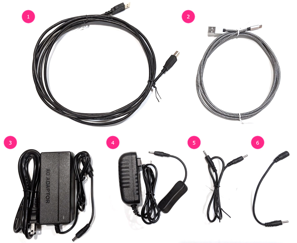
- USB A to B cable
- USB A to C cable (for test phone)
- 12V 2A power cord (for servo control box)
- 12V power cord (for lighting, with switch)
- 5V male-male connection cable (for lighting)
- 5V male-female conversion cable (for lighting)
Step 1: Connect lights
To connect the lights:
- Use the male-male cable to connect the two lights on the bottom ends of the lights as shown in figure 2. Secure the cable to the bottom of the box to keep the cable from interfering with the operation.
- Connect the end of the light closer to the light cable exit hole to
the conversion cable
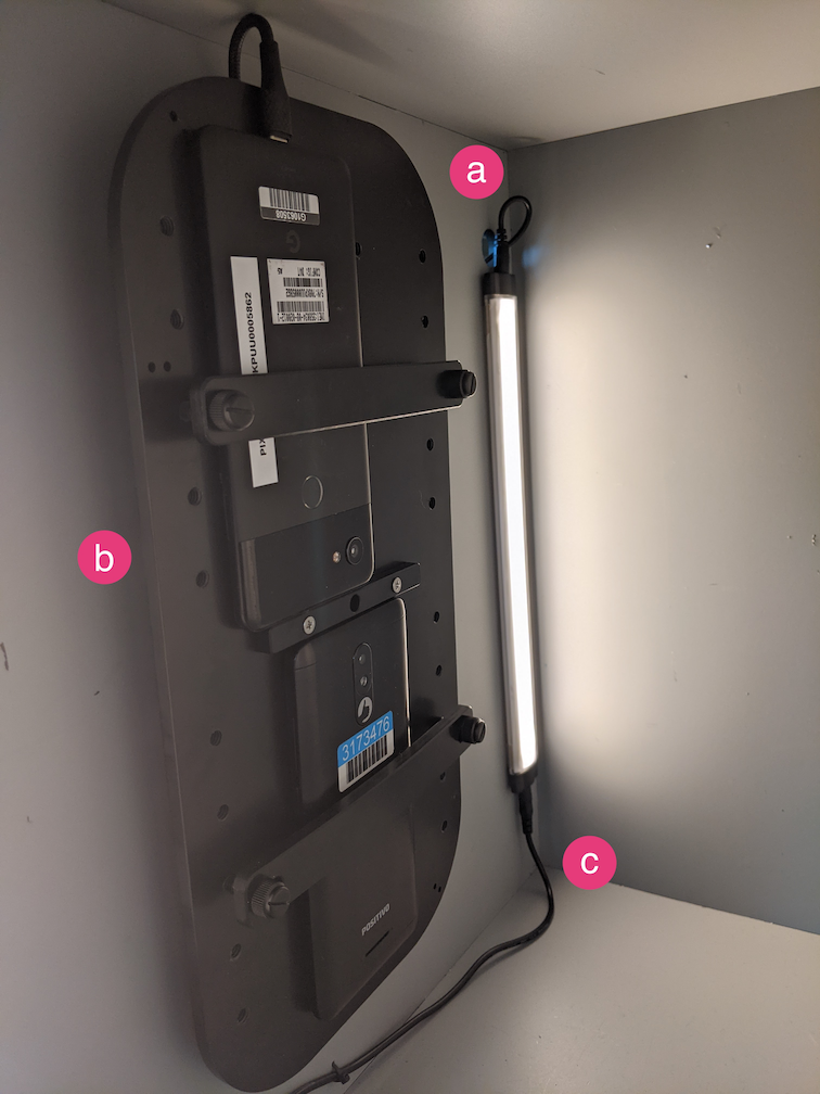
Figure 2. Connecting the lights to each other and one light to the conversion cable - Light cable exit hole
- USB cable exit hole
- 5V male-male conversion cable
- Thread the unconnected end of the conversion cable through the round
hole that exits the box, then connect it to the power
cable for lighting.
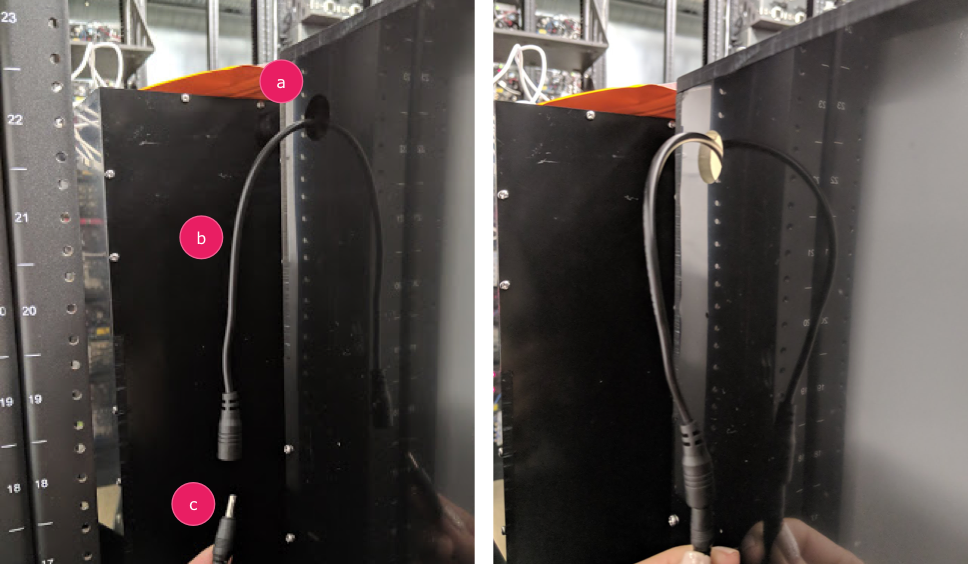
Figure 3. Lighting conversion cable exiting the box and connecting to power cable - Exit hole
- Conversion cable
- Power cable
Step 2: Attach servo
To attach the servo:
- Plug the servo connector into the servo control. Be sure to insert
the connector oriented to the corresponding colors as labeled (Y =
Yellow, R = Red, B = Black), as reversing the order could damage the
motor. If the cord is too short, use a
servo extension cable.
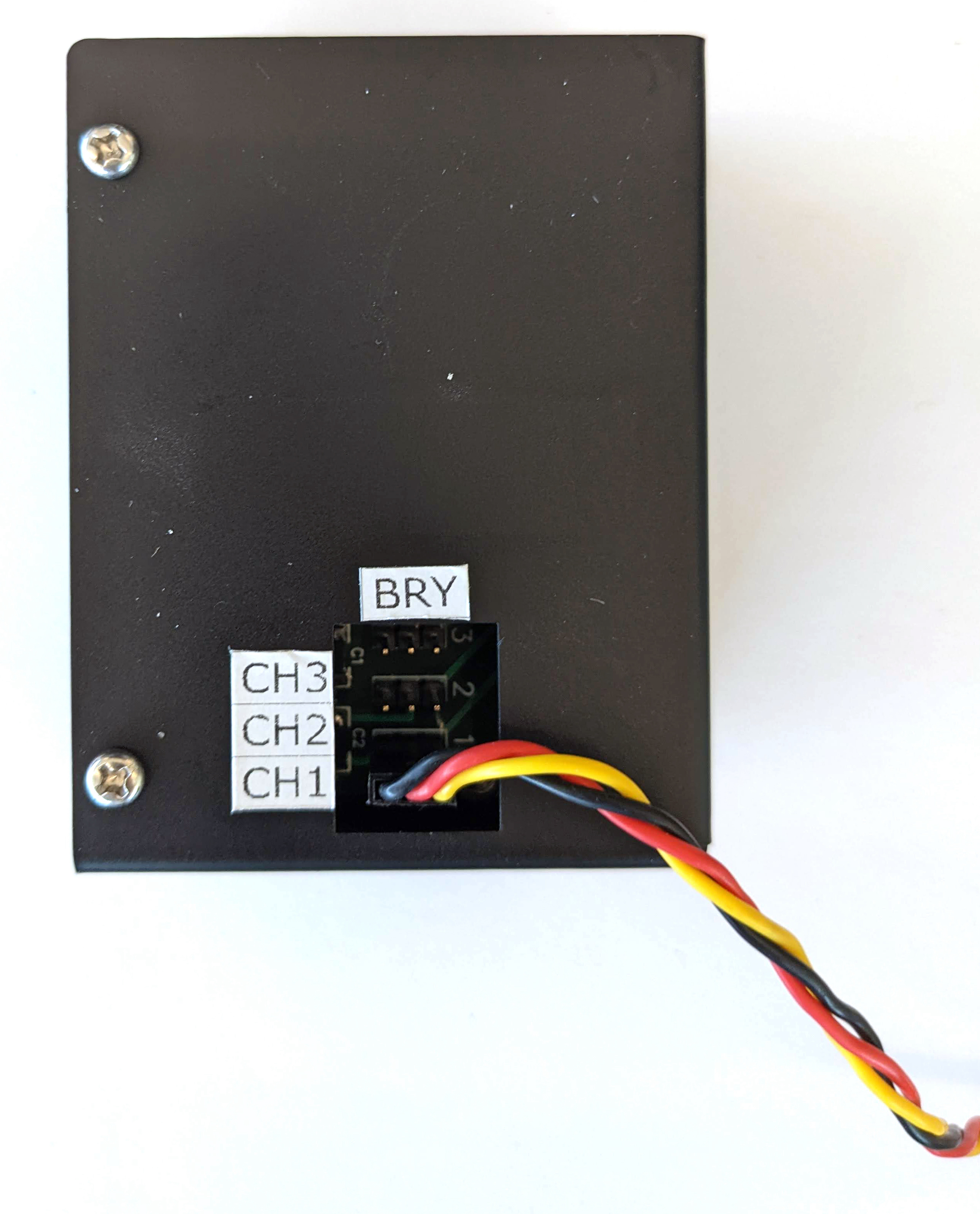
Figure 4. Servo connecting to the servo control box - Connect the servo control with its power cord (the lighting and
servo control have independent, dedicated power supplies).
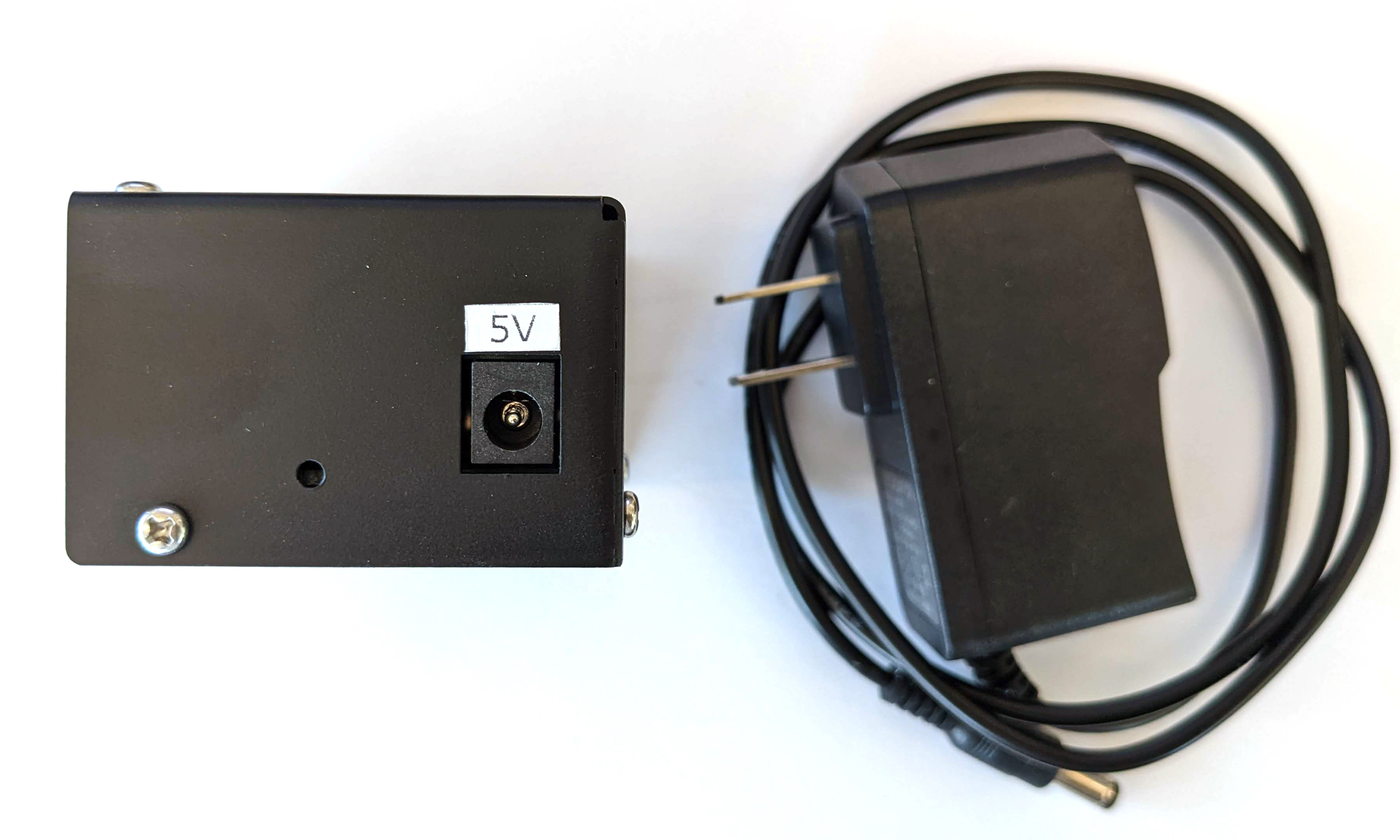
Figure 5. Connecting the servo control to its dedicated power cord - Use the USB A to B cable to connect the servo control box to the
host (machine that is running the test).
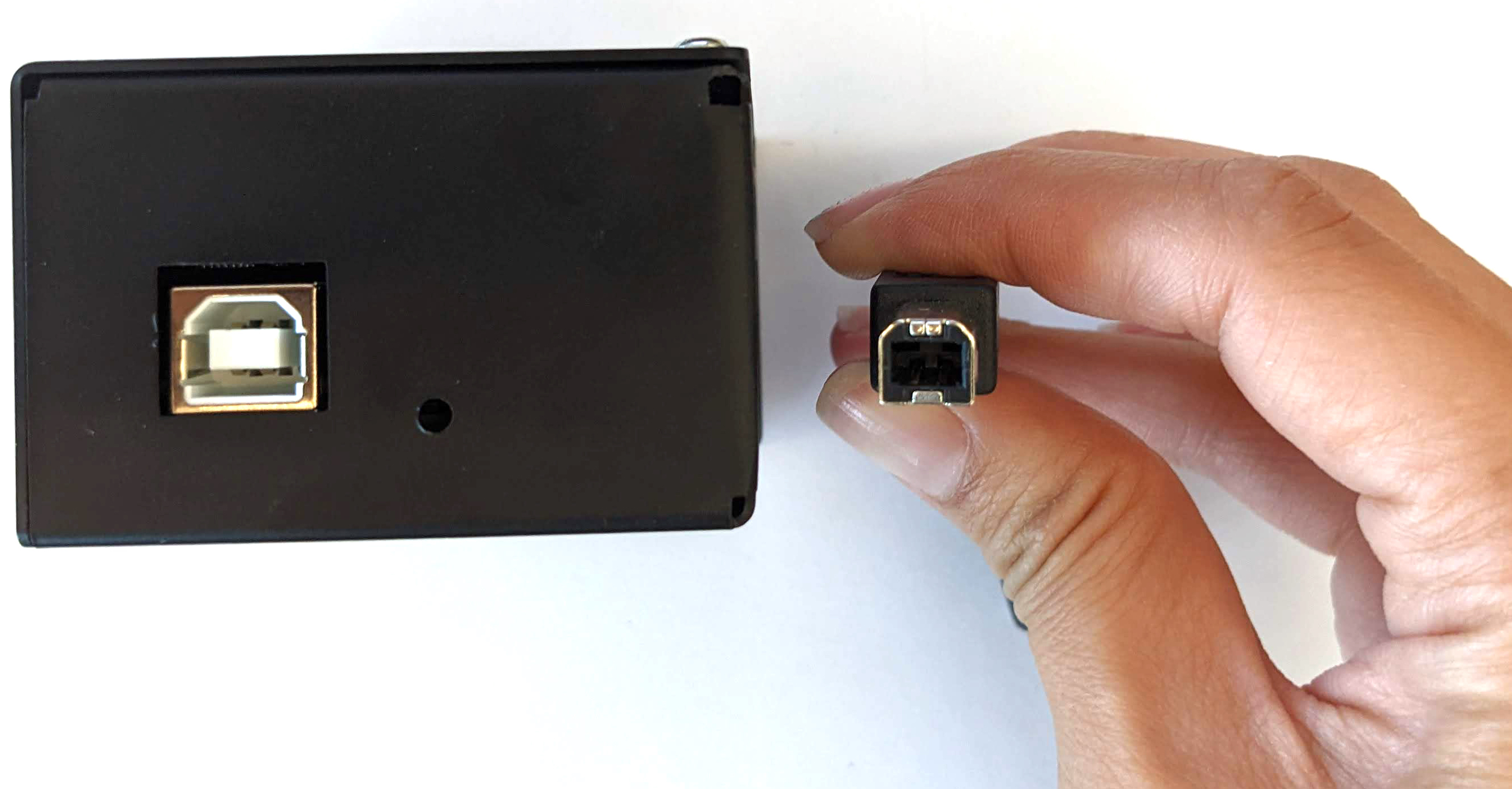
Figure 6. Connecting the servo control box to the host machine
Step 3: Attach phone
- Set the phone on the fixture and clamp it down. Tighten by turning the
nylon screw right.
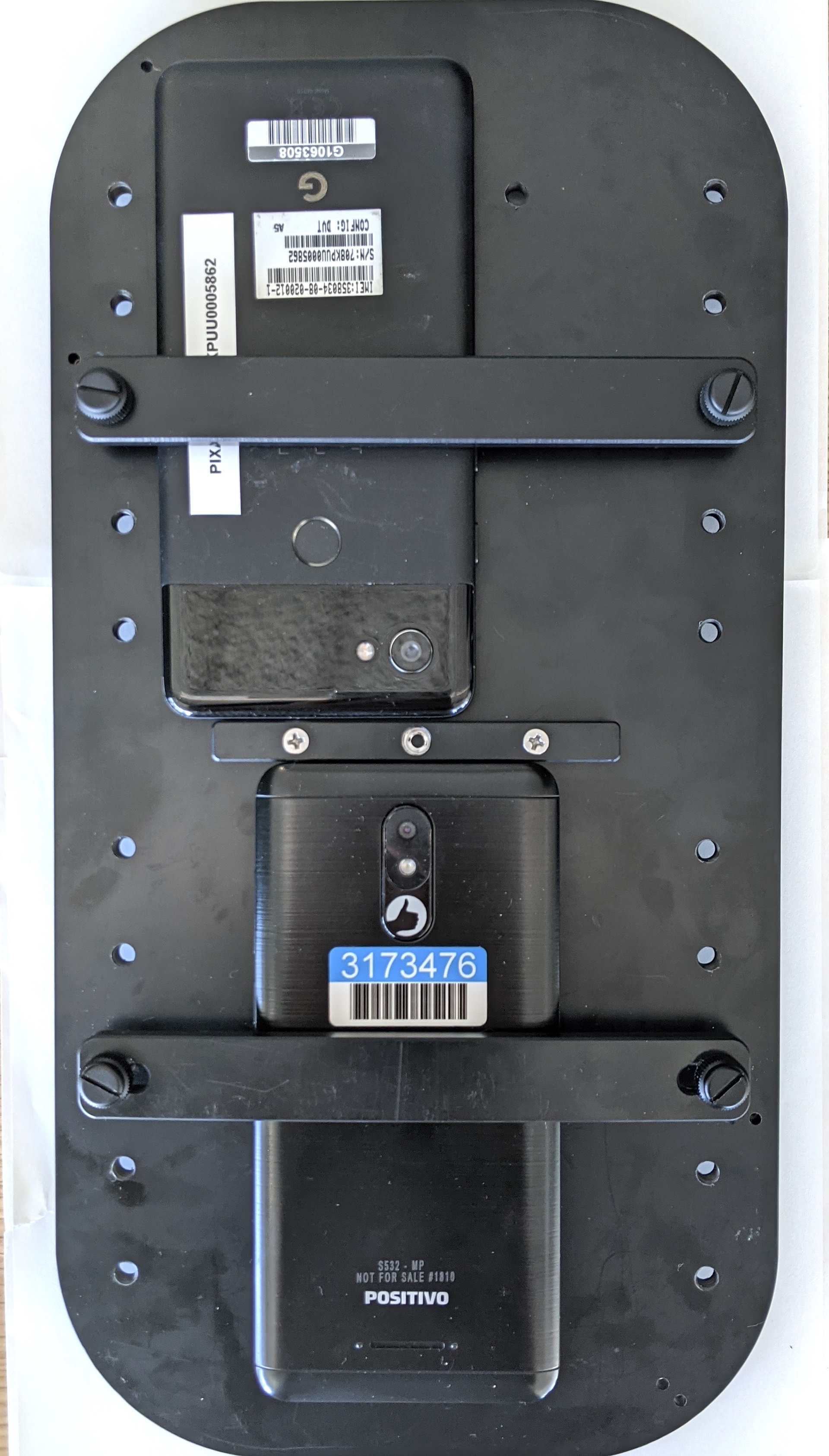
Figure 7. Placing and clamping the phone on the fixture Phones should be placed in a manner where the USB cords are located at the periphery of the phone mount and the cameras are near the center of the mount.
- Use a zip tie to hold the phone USB cord to the fixture plate and
lead it outside the box through the exit hole. Plug the other end
of the cord to the host running the test.
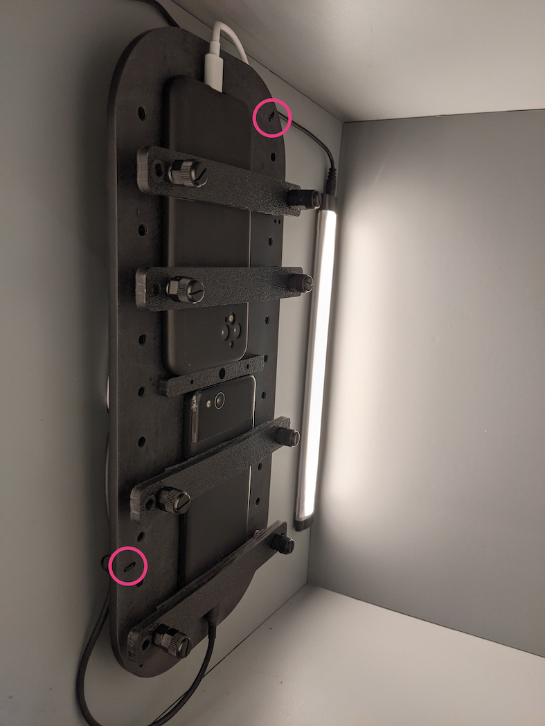
Figure 8. Phone USB cord held to fixture with zip ties
Step 4: Run test script
The main python executable for the test script is:
python tools/run_all_tests.py device=ID camera=0 scenes=sensor_fusion rot_rig=default
You can modify the command to specify the actual rotator address by using:
rot_rig=VID:PID:CH
- To determine the Vendor ID (VID) and Product ID (PID), use the Linux
command
lsusb. - By default, the VID and PID are set
to
04d8andfc73with channel "1".
Multiple runs, different formats
To perform multiple runs with different formats, you can use a
different script (however, the results will not be uploaded to
CtsVerifier.apk). Sample test script:
python tools/run_sensor_fusion_box.py device=FA7831A00278 camera=0 rotator=default img_size=640,360 fps=30 test_length=7Permission issues
To resolve permission issues related to controlling the motor through the USB port:
- Add the operator username to the
dialoutgroup using:sudo adduser USERNAME dialout - Log out the operator.
- Log in the operator.