
تقدّم هذه الصفحة معلومات حول كيفية شراء أو تجميع Sensor Fusion Box. يتم استخدام Sensor Fusion Box في اختبار CameraITS sensor_fusion واختبار
multi-camera المزامنة. ويوفّر بيئة اختبار متسقة لقياس دقة الطوابع الزمنية لأجهزة الاستشعار في أجهزة Android، وتحديدًا أجهزة استشعار صور الكاميرا وأجهزة الجيروسكوب. ويتألف من
مكوّنات صندوق بلاستيكي يتم قطعها بالليزر من
رسومات التصميم بمساعدة الكمبيوتر (CAD) وصندوق تحكّم في المحرك المؤازر.
يمكنك شراء Sensor Fusion Box أو إنشاء جهازك الخاص.
شراء جهاز Sensor Fusion Box
ننصحك بشراء Sensor Fusion Box من أحد المورّدين المؤهّلين التاليين.
شركة Byte Bridge Inc.
الولايات المتحدة: 1502 Crocker Ave, Hayward, CA 94544-7037
الصين: 22F #06-08, Hongwell International Plaza Tower A, 1600 West Zhongshan Road, Xuhui, Shanghai, 200235
www.bytebt.com
androidpartner@bytebt.com
الولايات المتحدة: +1-510-373-8899
الصين: +86-400-8866-490JFT CO LTD 捷富通科技有限公司 (المعروفة سابقًا باسم MYWAY DESIGN)
الصين: No. 40, Lane 22, Heai Road, Wujing Town, Minhang District, Shanghai, China
تايوان: 4F., No. 163, Fu-Ying Road, XinZhuang District, New Taipei City 242, Taiwan
www.jftcoltd.com
service@jfttec.com or its.sales@jfttec.com
China:+86-021-64909136
Taiwan: 886-2-29089060
إنشاء صندوق دمج بيانات المستشعرات
يتضمّن هذا القسم تعليمات مفصّلة حول تجميع صندوق Sensor Fusion من مكوّنات أكريلونيتريل بوتادين ستايرين (ABS) مقطوعة بالليزر (كما هو موضّح في الشكل 1).
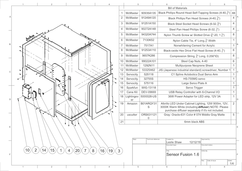
الشكل 1. رسم ميكانيكي لمكوّنات صندوق دمج المستشعرات
الأدوات المطلوبة
قبل البدء، تأكَّد من تنزيل الرسومات الفنية الخاصة بـ Sensor Fusion Box (المضمّنة في ملف Sensor Fusion Box المضغوط) وتوفُّر الأدوات التالية:
- مفكّ براغي برأس مصلّب
- مفك براغي برأس JIS
- مفاتيح سداسية
- طقم مِثقاب كهربائي
- سكين X-ACTO
- شريط
الخطوة 1: وضع الملصقات المصنوعة من الفينيل
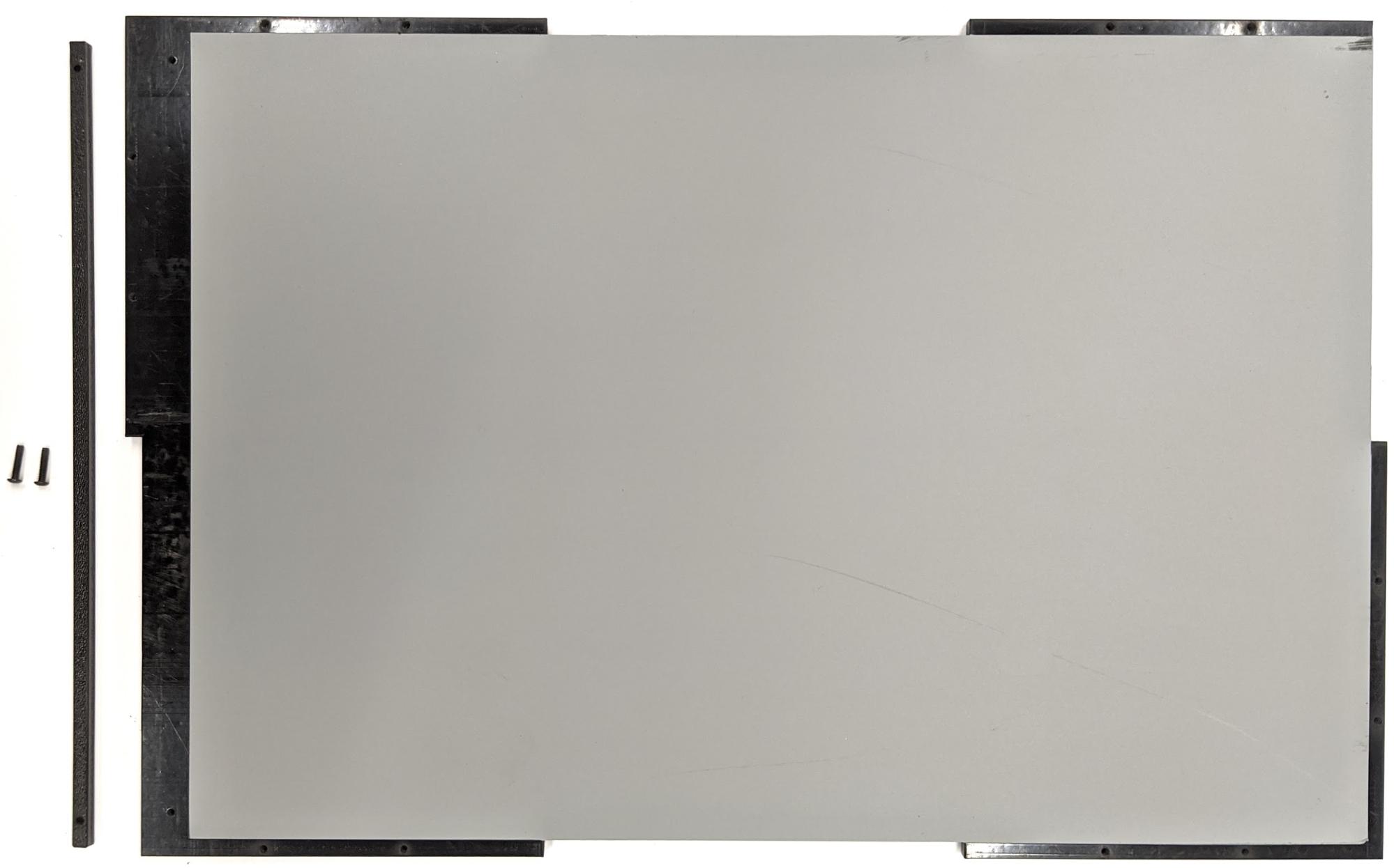
بعد إنشاء مكوّنات ABS باستخدام قاطع ليزر، ضَع ملصقات من الفينيل على العلبة البلاستيكية للحصول على التحكم المناسب في الألوان داخل علبة الاختبار:
ضَع الملصق على الجانب الأملس من مادة ABS كما هو موضّح في الشكل 2. للحصول على نصائح مفيدة حول تطبيق الملصقات المصنوعة من الفينيل، يُرجى الرجوع إلى wikiHow.
اقطع الثقوب اللازمة على الفينيل باستخدام سكين الحرفية.

الشكل 2. قطع ABS مع طبقة من الفينيل على الجانب الأملس (داخل العلبة)باستخدام غراء الأكريليك، ألصِق قطع ABS الدائرية على الزوايا الأربع للوحة السفلية.
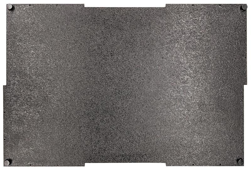
الشكل 3. لوحة سفلية مزوّدة بقطع دائرية من مادة ABS ملصقة في الزوايا الأربع
الخطوة 2: تجهيز حامل الهاتف وتركيب حامل المحرك المؤازر
لإعداد حامل الهاتف لتثبيته على المحرك المؤازر، اتّبِع الخطوات التالية:
انقر على 20 ثقبًا في أداة تثبيت الهاتف باستخدام مثقاب مقاس 1/4"-20.

الشكل 4. تركيبات هاتفية مزوّدة بفتحات ملولبةتأكَّد من توفّر فتحات ABS، وبراغي إبهام من النايلون، وصواميل من النايلون (لضبط ارتفاع البرغي إذا لزم الأمر)، ووصلة C1 ذات الأضلاع المتشابكة، وذراع مؤازر مزدوج من Actobotics، وبراغي 4-40، ونوابض مضغوطة.

الشكل 5. قطع حامل الهاتفضَع براغي 4-40 وشدّها (1.2 نيوتن متر أو 8.9 بوصة رطل قوة) على ذراع المحرك المؤازر في الجزء الخلفي من حامل الهاتف. باستخدام البراغي نفسها وصواميل الغطاء 4-40، اربط فتحة ABS الخاصة بفواصل الهاتف على الجانب الأمامي من حامل الهاتف.

الشكل 6. عمود في الجزء الخلفي من التركيب، يتم ربطه بإحكام باستخدام براغي يتم إدخالها من الأمام
الشكل 7. براغي بطول 1.9 سم (3/4 بوصة) وصواميل ذات غطاء 4-40
الشكل 8. الجزء الخلفي (على اليمين) والجزء الأمامي (على اليسار) من حامل الهاتف
الخطوة 3: ربط مشابك الهاتف
لربط مشابك الهاتف، اتّبِع الخطوات التالية:
قُصّ لوح النيوبرين وفقًا لشكل مشابك فتحة ABS، ولكن اترك مسافة أقصر بمقدار بوصة واحدة من كلا الطرفين كما هو موضّح في الشكل 9. بعد قطع لوح النيوبرين وفقًا لذلك، ضَع القطع على مشابك قطع ABS كما هو موضّح في الشكل 8.

الشكل 9. مشبك ABS مع وضع طبقة من النيوبرينثبِّت براغي الإبهام المصنوعة من النايلون وسلك الزنبرك بالمشبك. أضِف صواميل من النايلون لتقليل طول البراغي حسب الحاجة.

الشكل 10. مشبك مع لوح نيوبرين وبراغي إبهام وصواميل نايلون وسلك زنبركياربط براغي الإبهام الخاصة بمشابك الهاتف في الثقوب الملولبة الخاصة بتركيب الهاتف كما هو موضّح في الشكل 11. يمكنك تعديل موضع حاملَي الهاتفين حسب حجم الهاتفين.

الشكل 11. رسم ميكانيكي لتركيب الهاتف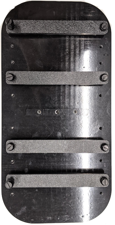
الشكل 12. تركيب الهاتف
الخطوة 4: تجميع قضيب الباب المنزلق
ثبِّت قضبان اللوحة المنزلقة في أعلى الصندوق وأسفله باتجاه الأمام. يوضّح الشكل 13 مسامير 6-32 على فتحات مُعدّة مسبقًا. يمكنك بدلاً من ذلك استخدام براغي ذاتية التثبيت.
الشكل 13. قضيب لوحة منزلقة ثابتة في أعلى وأسفل الصندوق
الخطوة 5: ربط جهاز الإضاءة
لربط حوامل الإضاءة والناشر:
ضَع قطعتَي المقبض فوق بعضهما البعض واربطهما باستخدام براغي 6-32 (أو استخدِم براغي ذاتية الربط).
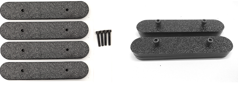
الشكل 14. قطع مقبض صندوق دمج البيانات الحسية وتجميعهأحضِر أربعة براغي وصواميل وصواميل على شكل بلوط بحجم 4-40 لتثبيت حامل التثبيت من مجموعة الإضاءة على جدار الصندوق.

الشكل 15. براغي 4-40 وحامل المصباح على الجدار الداخلي للعلبة
الشكل 16. البراغي والبراغي ذات الرأس المستدير المثبّتة على البراغي من خارج العلبةقُصّ موزع الضوء إلى حجم مناسب لتغليف شرائط الإضاءة (لا يلزم ذلك إذا كانت المصابيح مزوّدة بموزع).
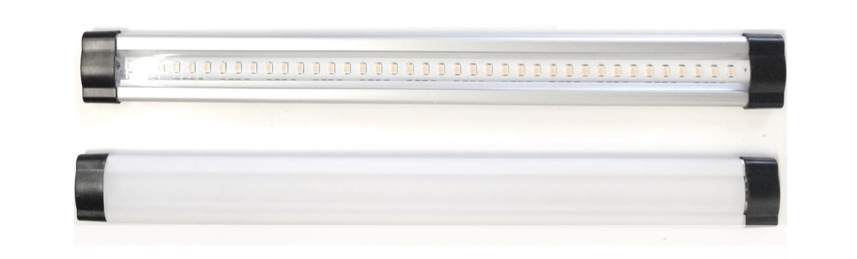
الشكل 17. شرائط وموزّعات الإضاءةلفّ موزع الضوء حول الشريط وتثبيته بشريط لاصق في الخلف

الشكل 18. شرائط وألواح تشتيت الضوء مثبّتة بشريط لاصق من الخلفثبِّت الأضواء في الأقواس (قد يكون التركيب محكمًا).
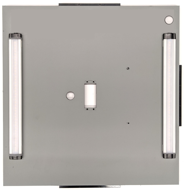
الشكل 19. المصابيح المثبّتة في أقواس
الخطوة 6: تثبيت أداة تثبيت الهاتف على لوحة المحرك المؤازر
لربط حامل الهاتف بلوحة المحرك المؤازر، اتّبِع الخطوات التالية:
أحضِر أربعة براغي 6-32 ولوحة مؤازرة لتثبيت المؤازرة على الحائط. ثبِّت المحرّك المؤازر على الجدار الداخلي وأدخِل البراغي من الداخل في لوحة المحرّك المؤازر على الجدار الخارجي.

الشكل 20. المحرّك المؤازر ولوحة المحرّك المؤازر مثبّتان في مكانهما باستخدام براغي 6-32ثبِّت تركيبات الهاتف على المحرك المؤازر باستخدام صواميل قفل (عن طريق دفع منتصف العمود إلى مركز دوران المحرك المؤازر).

الشكل 21. ترس مؤازر
باستخدام برغي المؤازرة المرفق مع المؤازرة، اربط (1.2 نيوتن متر أو 8.9 بوصة رطل قوة) أداة تثبيت الهاتف بترس المؤازرة من خلال ذراع المؤازرة.

الشكل 22. ذراع المؤازرة
الخطوة 7: التجميع النهائي
لإكمال تجميع صندوق Sensor Fusion Box، اتّبِع الخطوات التالية:
بدءًا من نظام التشغيل Android 13، يتوفّر جهاز اختبار دمج البيانات الحسية مع وحدة التحكّم في الإضاءة Arduino لنظام التشغيل Android 13. (في الإصدار 12 من نظام التشغيل Android أو الإصدارات الأقدم، تم شحن جهاز دمج البيانات الحسية مع وحدة تحكّم Arduino ذات 6 قنوات أو وحدة تحكّم Canakit. الأجهزة التي تعمل بالإصدارات من Android 11 إلى Android 12 متوافقة مع وحدة التحكّم في Android 13 أو وحدة التحكّم في Arduino ذات 6 قنوات أو وحدة التحكّم في Canakit.) وصِّل وصلة تمديد المحرك المؤازر بأي قناة في وحدة التحكّم بالمحرك المؤازر، حيث يتوافق GND مع السلك الأسود، وVCC مع السلك الأحمر، وSIG مع السلك الأصفر.
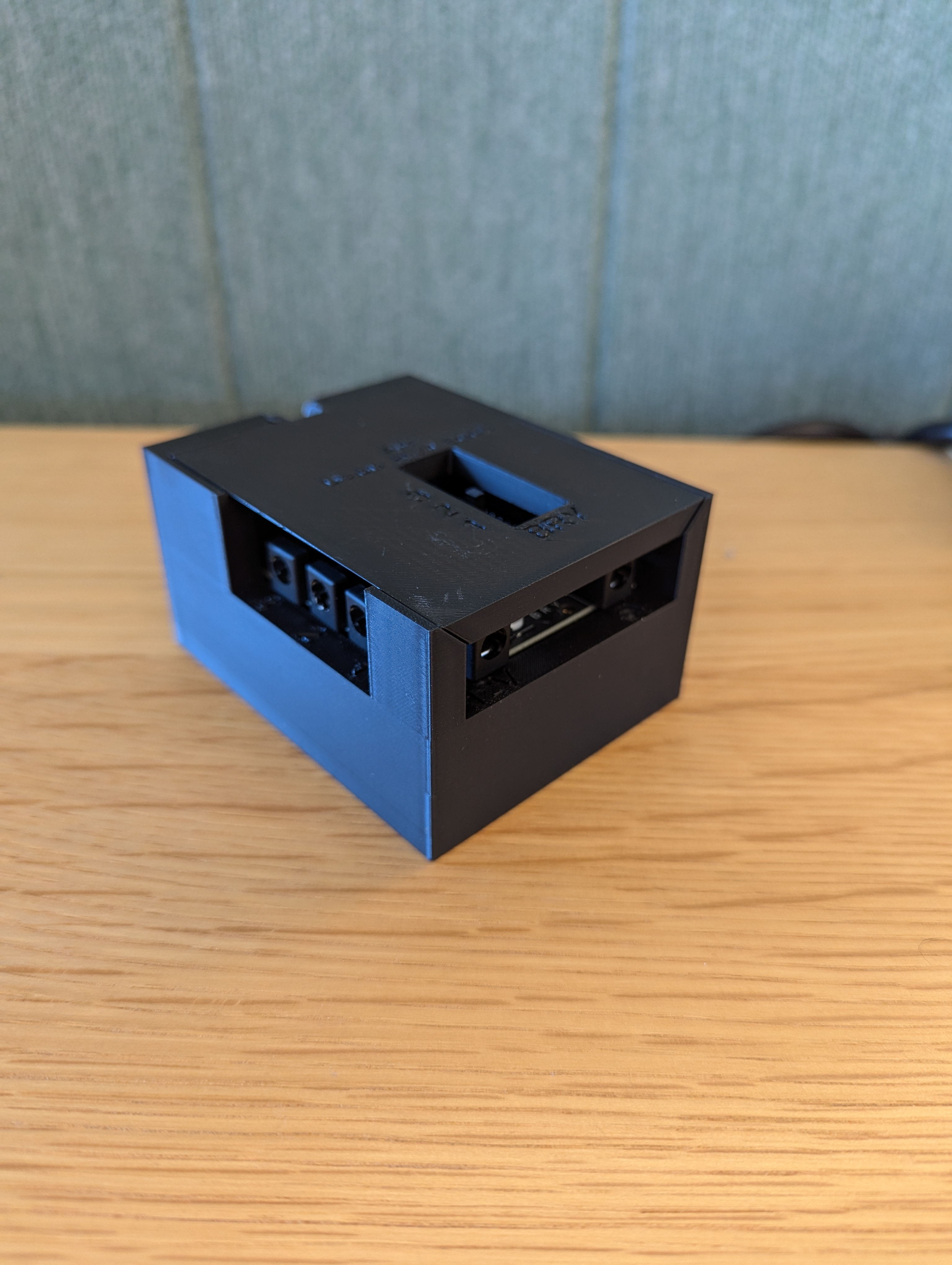
الشكل 23. Arduino Lighting Controller Rev3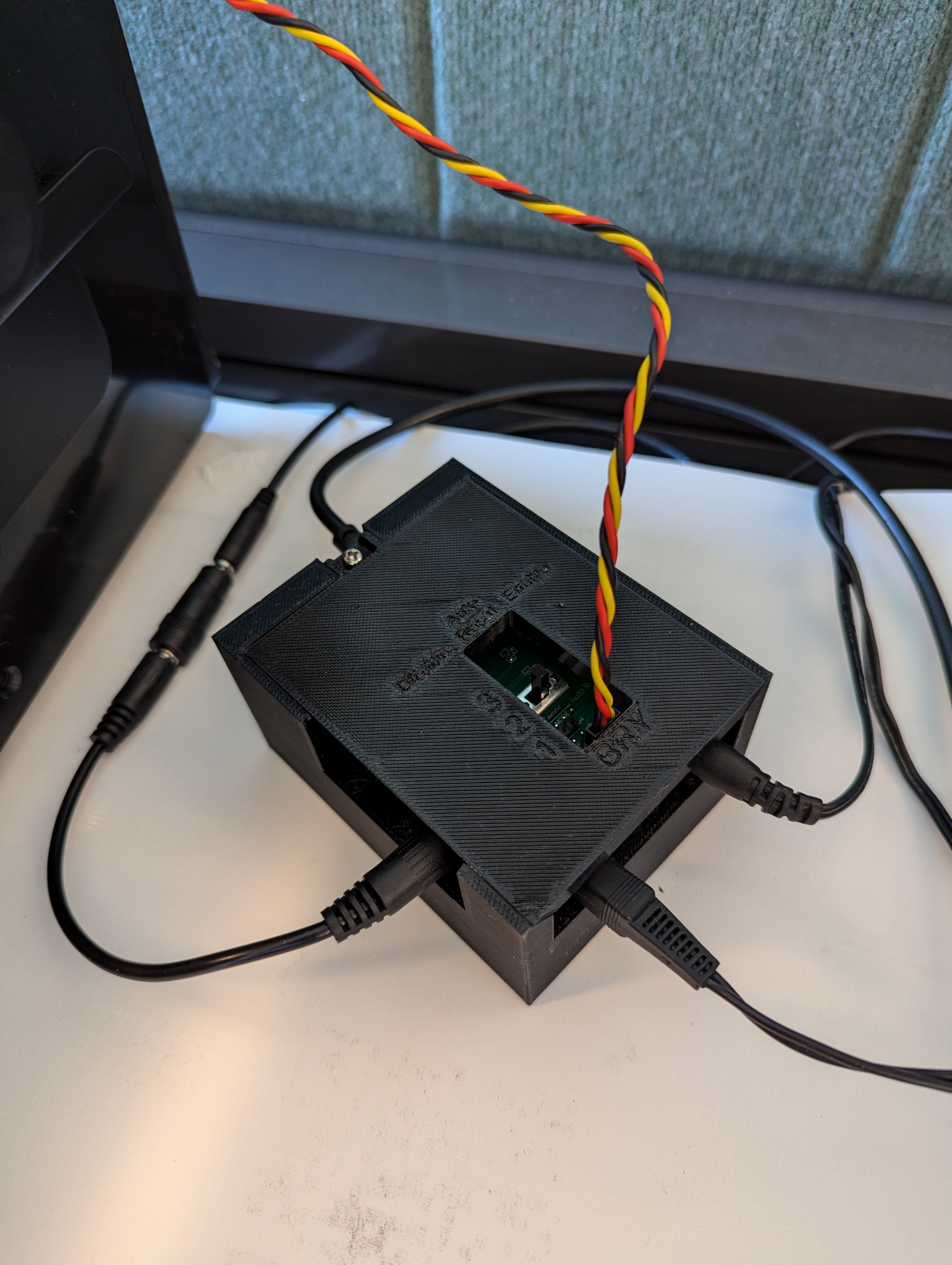
الشكل 24. نموذج اتصال وحدة التحكّم في الإضاءة Arduino Rev3ألصِق الصندوق بالشريط اللاصق، ثم اربط الأجزاء معًا (قد تحتاج إلى حفر ثقوب مسبقًا في بعض الأجزاء).

الشكل 25. جهاز اختبار دمج أجهزة الاستشعار المثبّتة
في الإصدار 15 من نظام التشغيل Android أو الإصدارات الأحدث، عليك العمل مع متجر الطباعة المحلي لطباعة ملف checkerboard.pdf (المضمّن في الدليل
test/sensor_fusionمن قاعدة الرموز البرمجية) على ورق مقاس 18 × 18 بوصة بنمط رقعة الشطرنج بعرض الورقة، ولصق الرسم البياني على الحائط المقابل لتركيب الهاتف.بالنسبة إلى الكاميرات التي تتضمّن مجالات عرض أصغر، مثل كاميرات التقريب البعيد، يمكنك التعاون مع متجر الطباعة المحلي لإنشاء نُسخ من لوحة المربّعات ذات حجم متناسب. (على سبيل المثال، سيتم طباعة مخطط بمقياس% 50 على ورق بحجم 9 × 9 بوصة).
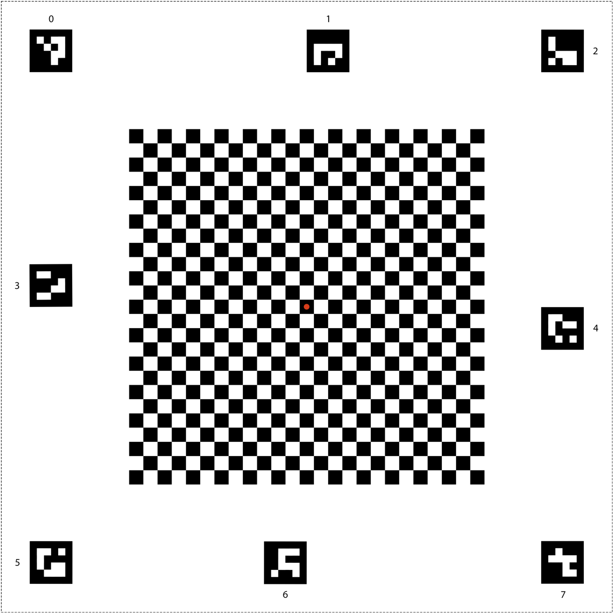
الشكل 26. رسم بياني على شكل رقعة الشطرنج لنظام التشغيل Android 15 أو الإصدارات الأحدث
تأكَّد من أنّ النقطة الحمراء في وسط لوحة المربّعات تواجه الكاميرا مباشرةً عند وضعها على أداة التثبيت، كما هو موضّح في الشكل 27.
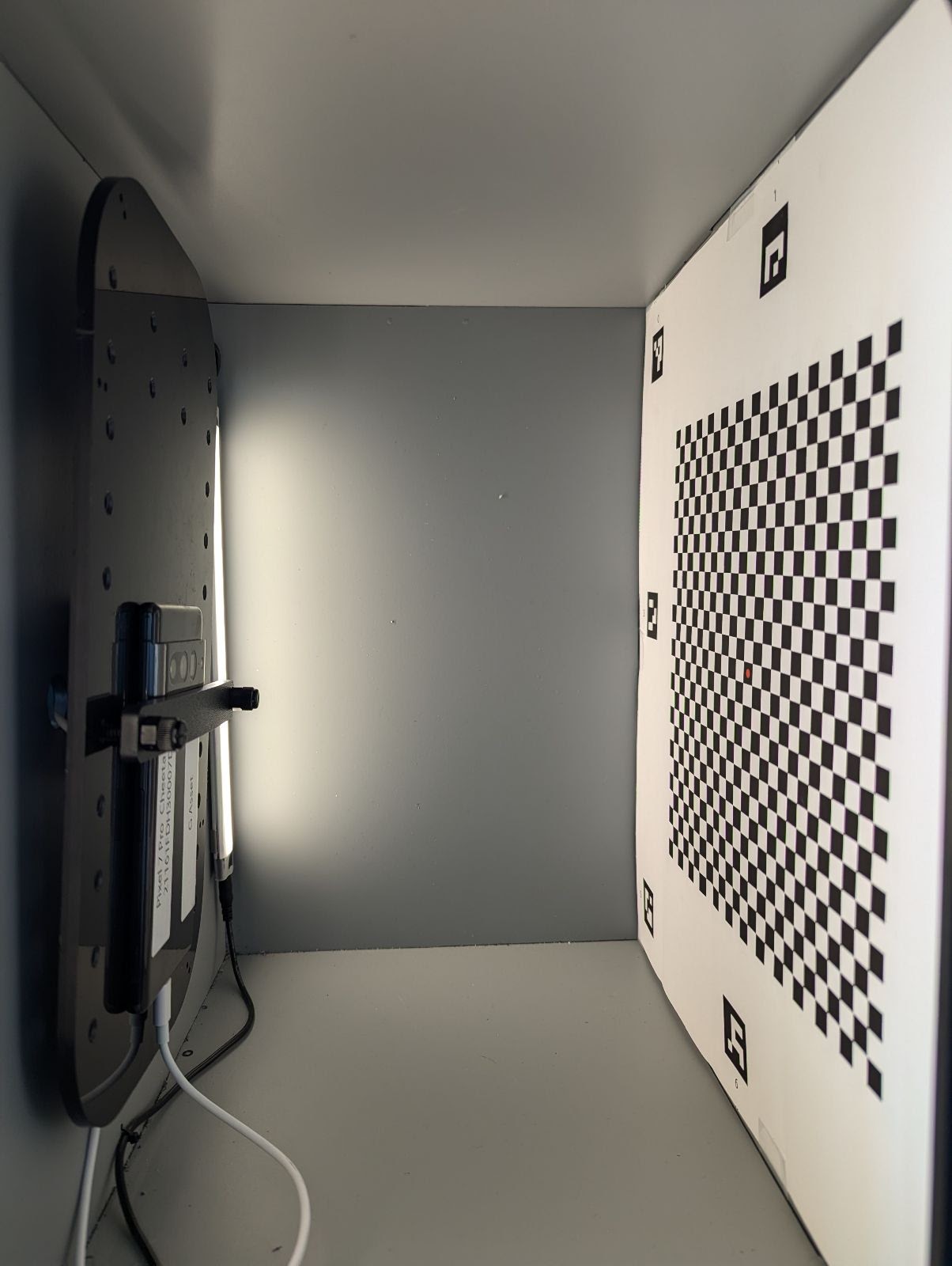
الشكل 27. لوحة مربّعات مطبوعة ومثبّتة بشريط لاصق على الجدار المقابل لجهاز تثبيت الهاتف