本页介绍了如何组装 Android 13 控制器,该控制器用于控制传感器融合测试装置的移动以及盒装 ITS 的照明。传感器融合测试是兼容性测试套件 (CTS) 中的相机图像测试套件(相机 ITS)的一部分。与以前的控制器版本相比,Android 13 控制器旨在简化组装并降低成本。此外,还有以下优势:电子元件和伺服器之间可以实现电源隔离,并且可通过单个控制器控制最多 3 个伺服器和 3 个灯。
Android 13 控制器概览
测试装置中的伺服器和照明控制
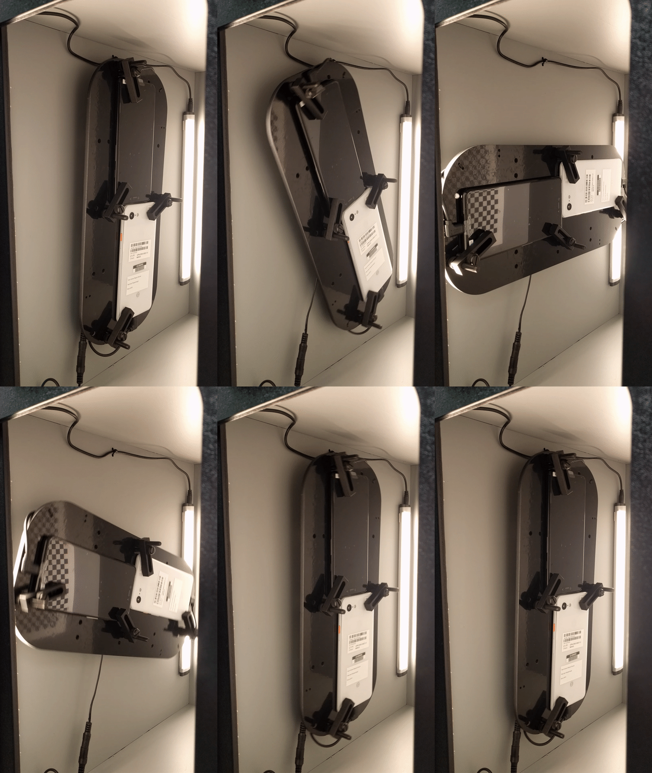
传感器融合测试装置让手机在固定范围内移动,以进行可重现的测试。对着带有方格图案的拍摄目标旋转手机,以便在不同位置拍摄图片。对于 test_sensor_fusion,伺服器将手机围绕摄像头轴中心旋转 90 度,并在大约 2 秒内将手机旋转回原位。对于 test_video_stabilization,伺服器将手机围绕摄像头轴中心旋转 10 度,然后将手机旋转回原位,如此反复,从而模仿在步行拍视频时手机的移动情况。图 1 显示了在传感器融合测试装置中移动的两部手机。图 2 显示了在传感器融合测试装置中移动的一部手机。
盒装 ITS 提供了在测试平板电脑和测试手机之间具有固定距离的一致测试环境,此外还提供了没有外部光源的一致照明。对于 test_auto_flash,需要一个所有灯都已关闭的黑暗环境,才能在测试手机上触发自动闪光灯功能。图 3 显示了盒装 ITS 中的灯由 Android 13 控制器关闭和开启。

图 1. test_sensor_fusion 测试装置中的手机移动

图 2. test_video_stabilization 测试装置中的手机移动

图 3. 为 test_auto_flash 关闭和开启灯
伺服电机控制
测试装置中的模拟伺服电机是采用脉冲宽度调制 (PWM) 控制的位置伺服器。图 3 显示了一个典型的位置控制示例。控制信号的周期为 20 毫秒。如果将脉冲宽度更改为最小宽度,电机会移动到空挡位置;如果将脉冲宽度更改为最大宽度,电机会顺时针旋转 180 度。

图 4. 典型的伺服控制说明
视频教程
此视频教程介绍了如何设置 Android 13 控制器。
修订历史记录
下表介绍了相机 ITS WFoV 装置的修订历史记录,并添加了指向每个生产文件版本的下载链接。
| 日期 | 修订版本 | 下载生产文件 | 更新日志 |
|---|---|---|---|
| 2022 年 12 月 | 1.1 |
|
|
| 2022 年 3 月 | 1 |
|
Android 13 控制器实现
为了通过主机控制伺服电机移动和照明,传感器融合测试装置需要 USB 连接。Android 13 控制器使用一个顶部安装了自定义布线板(或护罩)的 USB 连接 Arduino UNO R3 板。采用开源在线 PCB 设计工具设计的两层护罩可以在以下位置获得:https://oshwlab.com/leslieshaw1023/cameraits_arduino_shield_populated。自定义布线护罩的俯视图和仰视图如图 5 和图 6 所示。

图 5. 自定义布线护罩(俯视图)

图 6. 自定义布线护罩(仰视图)
Android 13 控制器可以通过单个主机控制最多 3 个传感器融合装置和三个盒装 ITS。俯视图显示了用于沿中轴安装三个 3 脚电机针座的丝网印刷轮廓和三个 LED 电源插孔。俯视图显示了插接 UNO、5 V 电源插孔和 10 uF 旁路电容器所需的 4 脚和 8 脚针座连接的丝网印刷轮廓。
为了隔离伺服电流和照明电流,伺服电源由外部 5 V 插孔提供。UNO 电子元件通过 USB 连接器单独驱动,二块布线板之间不会共享电源。请注意,UNO 中现有的外部电源插孔未使用;为了避免给控制器供电时产生混乱,该插孔封装在外壳设计中。

图 7. 连接到 Android 13 控制器的照明和 12V 电源
根据照明电源的插头尺寸,酌情使用适配器。

图 8. 将照明电源连接到控制器的适配器
组装 Android 13 控制器
物料清单 (BOM)
| 数量 | 说明 | 部件号/链接 |
|---|---|---|
| 1 | 1.6 毫米厚的 CameraITS Arduino 护罩 | https://oshwlab.com/leslieshaw1023/cameraits_arduino_shield_populated |
| 1 | Arduino UNO R3 | https://store.arduino.cc/usa/arduino-uno-rev3 |
| 6 | 2.1x5.5 毫米,5 V 通孔,直角枪形插孔 | 101179 |
| 2 | 35 V,10%,10 uF 钽质电容器 | 2290863 |
| 2 | 50 V,5%,100 pF 陶瓷 1206 贴装电容器 | 12065A101JAT2A |
| 3 | 1 千欧,表面贴装电阻器 | CRCW08051K00FKEAC |
| 3 | 电源 MOSFET | RFP30N06LE |
| 3 | 1 排 3 脚,间距 100 密耳(2.54 毫米),通孔公形针座 | 732-5316-ND |
| 1 | 1 排 8 脚,间距 100 密耳(2.54 毫米),通孔公形针座 | 732-5321-ND |
| 1 | 1 排 4 脚,间距 100 密耳(2.54 毫米),通孔公形针座 | 732-5317-ND |
| 3 | 11 毫米母形对母形尼龙压铆螺母柱(5 毫米宽,M3-0.5 螺纹) | 92319a317 |
| 4 | 6 毫米公形对母形尼龙压铆螺母柱(5 毫米宽,M3-0.5 螺纹) | 95783a004 |
| 3 | M3-0.5 6 毫米平头尼龙螺钉 | 92492A716 |
| 4 | M3-0.5 8 毫米平头机用螺钉 | XM2510008A20000 |
| 2 | M3-0.5 6 毫米平头机用螺钉 | XM2510006A20000 |
| 6 | 4 号,1/2 圆头钣金螺钉 | 90925A110 |
| 1 | 5 V,15 W UL 认证电源,2.1x5.5 毫米插头(电机) | KSAS0180500300VU-VI |
| 1 | 12 V,60 W UL 认证电源,2.1x5.5 毫米插头(灯) | GSM60A12-P1J |
所需的其他工具
- 焊铁、焊料、吸锡器
- 小号十字头螺丝刀
- T10 号梅花头螺丝刀
填充布线板
使用与丝网印刷轮廓匹配的部件填充布线板的顶部和底部。对布线板的顶部而言,可以通过把公形针座放入 Arduino 板的恰当位置并把布线板放到连接器顶部来对齐公形针座。然后可以通过将 1x8 和 1x4 针座焊接到恰当位置,来保证 Arduino 和布线板充分对齐。可以对电源插孔进行同样的操作,但需要用一个垫片才能确保组装紧密,因为电源插孔在组装完毕后不会紧贴着 Arduino。旁路电容器焊接完毕后,布线板顶部可以填充六个用于电机控制的 1x3 公形针座。请注意,针座的朝向应该使连接器按扣底部面向电机,从而给电机座留下最大空间。
所有组件焊接到恰当位置后,就可以使用压铆螺母柱和螺钉组装系统。四个公形对母形 6 毫米压铆螺母柱可以在 Arduino 和塑料外壳底部之间提供机械稳定性。但是,Arduino 和自定义护罩之间只有三个 11 毫米母形对母形压铆螺母柱,因为 Arduino 上有一个孔(SCL 针附近的孔)由于靠近 Arduino 上的母形针座而无法使用。将三个母形对母形压铆螺母柱旋到三个公形对母形压铆螺母柱上,从而将压铆螺母柱旋到 Arduino 上。然后使用三个 M3 螺钉将布线板护罩固定到压铆螺母柱上。图 9 显示了 Arduino 护罩的示意图。

图 9. Arduino 护罩示意图
控制器外壳
控制器包含自定义外壳。组装好的控制器可通过旋入外壳底板的四颗沉头螺钉安装到外壳上。使用六颗圆头组装螺钉和两颗平头组装螺钉来组装外壳。伺服和 5 V 外部电源等相关信息蚀刻在塑料顶部。图 10 是组装好的外壳内部的控制器的照片。

图 10. 外壳内的填充护罩和组装好的系统
来自主机的控制软件
可将微代码下载到 UNO,为电机信号分配 PWM 针脚,并为不同角度定义脉冲宽度范围。有关用于六台 HS-755MB 电机的伺服旋转控制的微代码,请参阅其他资源。该部分还包括一个名为 rotator.py 的简易程序的链接,该程序可以使伺服器旋转。
使用 Android 13 控制器
相机 ITS 的使用:
python tools/run_all_tests.py device=device_id camera=0 rot_rig=arduino:1 scenes=sensor_fusion
使用附带的测试脚本:
python rotator.py --ch 1 --dir ON --debug
旧版控制器和兼容性
修订版 2 控制器和修订版 1 控制器(如图 11 和 12 所示)与 Android 13 不兼容,并且不支持 test_preview_stabilization、test_video_stabilization 和 test_auto_flash,因为它们无法实现防抖和照明控制所需的精细移动。

图 11. 修订版 2 Arduino 控制器

图 12. Cana kit 控制器
